Image forming apparatus including line head

a line head and forming apparatus technology, applied in the direction of printing, inking apparatus, etc., can solve the problems of increasing the cost of the head, affecting the production yield, and the need to replace the entire line head

Active Publication Date: 2008-10-07
RISO KAGAKU CORP
View PDF4 Cites 19 Cited by
  • Summary
  • Abstract
  • Description
  • Claims
  • Application Information

AI Technical Summary

Benefits of technology

[0009]According to the present invention, there is provided an image forming apparatus including a recording head portion having a configuration in which a plurality of small heads are alternately arranged in a width direction of a recording medium to have an overlap at each end portion thereof so that a virtual long line head is constituted, and each head can be individually replaced by easy attachment / detachment.

Problems solved by technology

As the line head, there is also a type constituted of one long head which is a so-called line head, but such a head has a bad production yield and a problem of an increase in cost of the head.
However, when there is a nozzle which cannot eject an ink because of damage or the like caused due to clogging or jam of the nozzle after incorporation in an image forming apparatus, the entire line head must be replaced.
Further, Jpn. Pat. Appln. KOKAI Publication No. 2004-306261 discloses a configuration in which the individual heads are arranged in a zigzag pattern and there are many tubes which supply an ink to the individual heads or control wiring lines which supply an electrical signal, which results in complicated attachment / detachment or adjustment of each head.

Method used


Image

  • Image forming apparatus including line head
  • Image forming apparatus including line head
  • Image forming apparatus including line head

Examples


first embodiment

[0045]FIGS. 1 to 4 show an appearance configuration of a recording head portion mounted in an image forming apparatus according to the present invention.

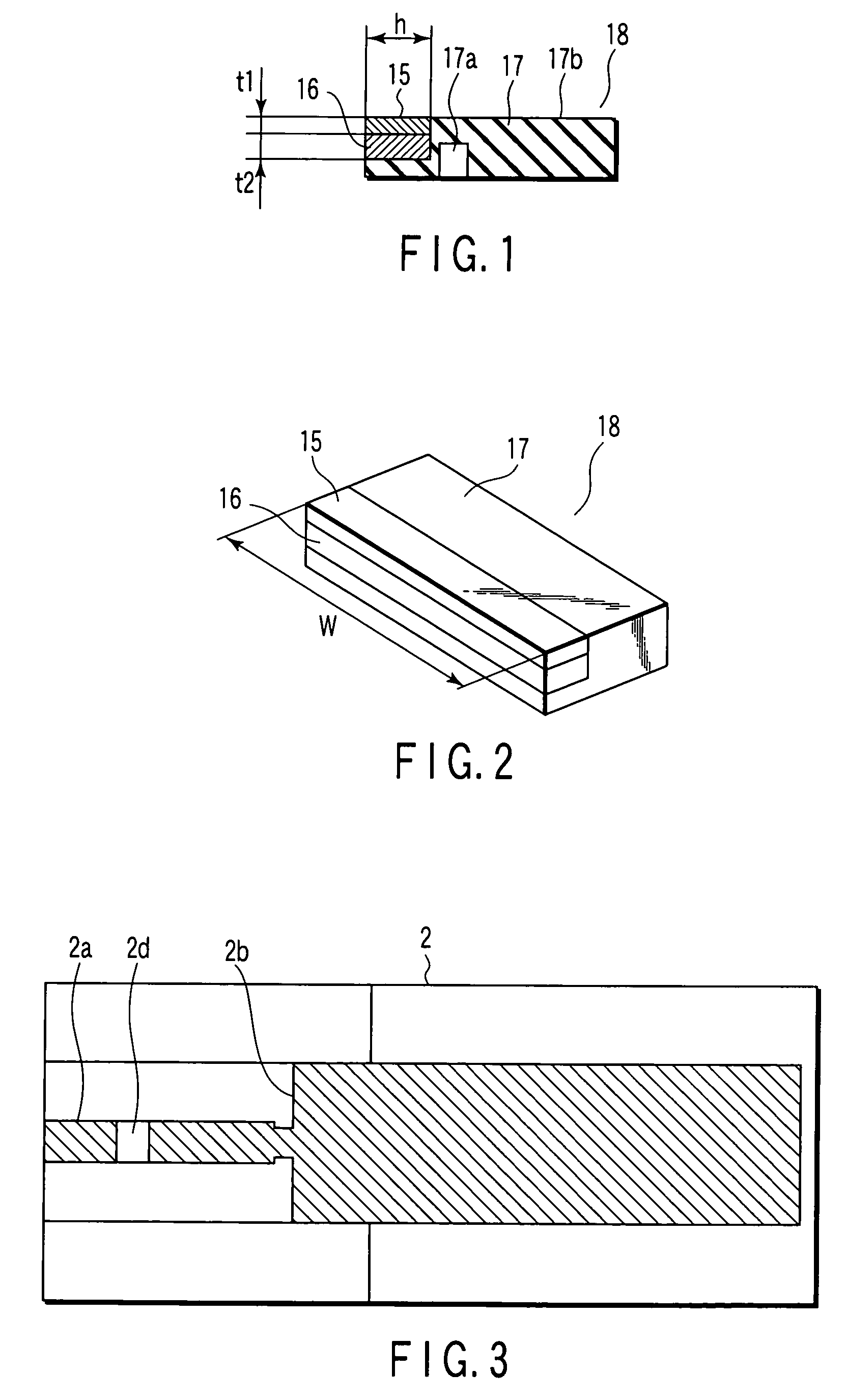
[0046]First, FIG. 1 shows an example of a piezo structure of a part which ejects an ink. This structure is obtained by attaching two piezo plates 15 and 16 having the same characteristics but different polarizing directions. These piezo plates 15 and 16 have the same length, and a length with a width W=approximately 60 mm is assumed so that approximately 300 eject nozzles can be arranged at intervals of 150 dpi in this example. Further, in regard to a thickness, the piezo plate 15 has a thickness t1=150 μm and the piezo plate 16 has a thickness t2=300 μm. A combined thickness is approximately 450 μm, and a length h in a short side direction is approximately 3.5 mm. The attached piezo plates 15 and 16 are bonded to a piezo plate 17 having different characteristics, thereby constituting such a piezo structure 18 as shown in FIG. 2. In...

second embodiment

[0076]A second embodiment according to the present invention will now be described.

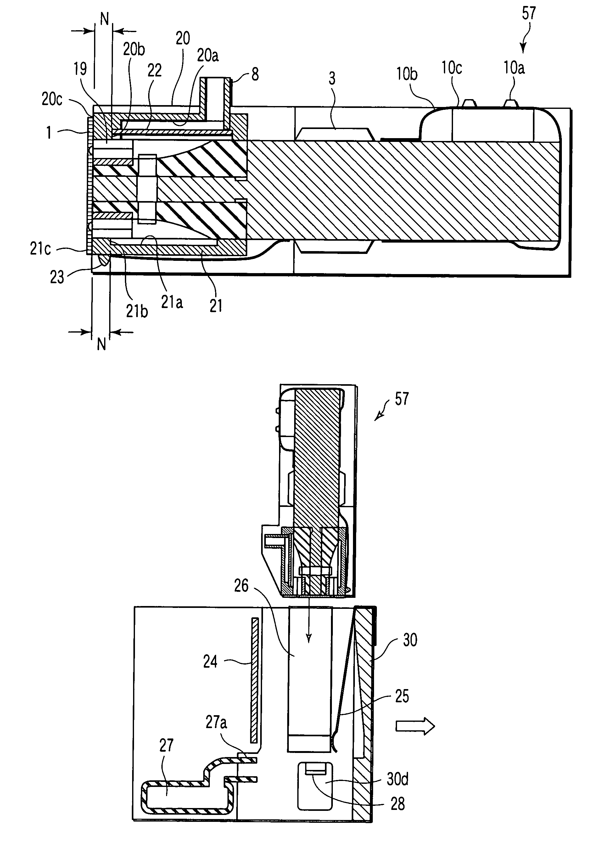
[0077]FIG. 20 is a view showing an attachment method of a head module 57 according to a different conformation. This embodiment is different from the first embodiment in three points. The first point is that an ink port 8 is bent into an L shape along the way and its opening faces a nozzle plate 1 side. The second point is that a power feed portion 10 is provided on an end surface of a base 2 opposite to the nozzle plate 1. The third point is that a cover 21 covers a drive IC 3 and has a shape in which one end is extended to a position close to the power feed portion 10.

[0078]FIG. 21 is a view showing this head module 57 from the power feed portion 10 side. Two dashed lines 1b which are drawn at the center and parallel with each other indicate positions of nozzle arrays 1b provided on the nozzle plate 1 on the opposite side from which an ink can be injected.

[0079]In this module, a nozzle array interva...

third embodiment

[0128]FIGS. 32A and 32B are views showing cross-sectional configurations in states where head modules are not inserted into a head mount and where the head modules are inserted into the head mount according to a

[0129]This embodiment is different from the constitution shown in FIGS. 25A and 25B in the arrangement of the ink path portion and the configuration the ink joint.

[0130]In an intermediate position of the head mount 30, the ink pass portion 61 extends in a line in a width direction of a recording medium. On the uppermost surface of the ink path portion 61, an opening portion 61a is disposed. An end portion of an ink port 62 of the head module 57 is provided with a tube made of a resin, a rubber or the like having elasticity. The ink port 62 is inserted into the opening portion 61a, whereby the head module 57 can be linked with the ink path portion without any leakage of the ink.

[0131]That is to say, when the head module 57 is inserted as shown in FIG. 32B, a tip portion of the...


PUM


Abstract

An image forming apparatus has a recording head portion constituted of head modules having a configuration in which a plurality of small heads are detachably attached in a head mount at alternate positions in a recording medium width direction and a drive portion is also mounted.

Description

CROSS-REFERENCE TO RELATED APPLICATIONS[0001]This application is based upon and claims the benefit of priority from prior Japanese Patent Application No. 2005-024388, filed Jan. 31, 2005, the entire contents of which are incorporated herein by reference.BACKGROUND OF THE INVENTION[0002]1. Field of the Invention[0003]The present invention relates to an image forming apparatus including a line head which realizes high-speed image formation.[0004]2. Description of the Related Art[0005]In general, there is a printer including a line head, in which a plurality of injection nozzles which eject inks of a black color or a plurality of colors are arranged in a linear state, thereby realizing high-speed image formation. In this line head, a plurality of injection nozzles are arranged face to face over a width of a recording medium to be carried so that an image can be formed along an overall width of the recording medium when the recording medium is transmitted only once. As the line head, th...

Claims


Application Information

Patent Timeline
Patent Type & Authority Patents(United States)
IPC IPC(8): B41J2/14B41J2/16
CPCB41J2/15B41J2202/19B41J2202/20B41J2/14209B41J2202/08
Inventor YAMADA, TAKAHISA
Owner RISO KAGAKU CORP
Why Eureka
Try Eureka