
Wideband radar

a wideband radar and wideband technology, applied in the field of wideband radar, can solve the problems of high dynamic range requirements in the a/d-converter, high jamming sensitivity, and low velocity resolution compared with the range resolution, so as to achieve the effect of reducing range resolution, range resolution, and velocity resolution

Active Publication Date: 2008-10-07
TELEFON AB LM ERICSSON (PUBL)
View PDF2 Cites 3 Cited by
  • Summary
  • Abstract
  • Description
  • Claims
  • Application Information

AI Technical Summary

Benefits of technology

[0034]One advantage of this procedure is that all jammed frequency sub bands will be excluded in the calculation of the average value. For example, a 1 bit A / D converter may be used and the procedure excluding jammed parts of the frequency band gives graceful degradation.
[0035]The present invention has the advantage of gaining velocity resolution at the price of reduced range resolution, but where the range resolution still is good enough for detecting moving targets such as air planes etc. The invention also gives a system with high immunity against interference and reduced dynamic range requirements in the A / D-converters.

Problems solved by technology

A challenge in the design of broadband radar systems is to achieve velocity resolution as good as the range resolution.
Problems with existing solutions are low velocity resolution compared with the range resolution.
There is also a problem with a high jamming sensitivity since it is not possible to exclude jammed parts of the frequency band.
Furthermore, there is also a problem with high dynamic range requirements in the A / D-converters since jammed parts of the used frequency band cannot be excluded before the A / D-converter and the dynamic range in the A / D-converters must be able to handle the level of the jamming signal.

Method used


Image

  • Wideband radar
  • Wideband radar
  • Wideband radar

Examples


Embodiment Construction

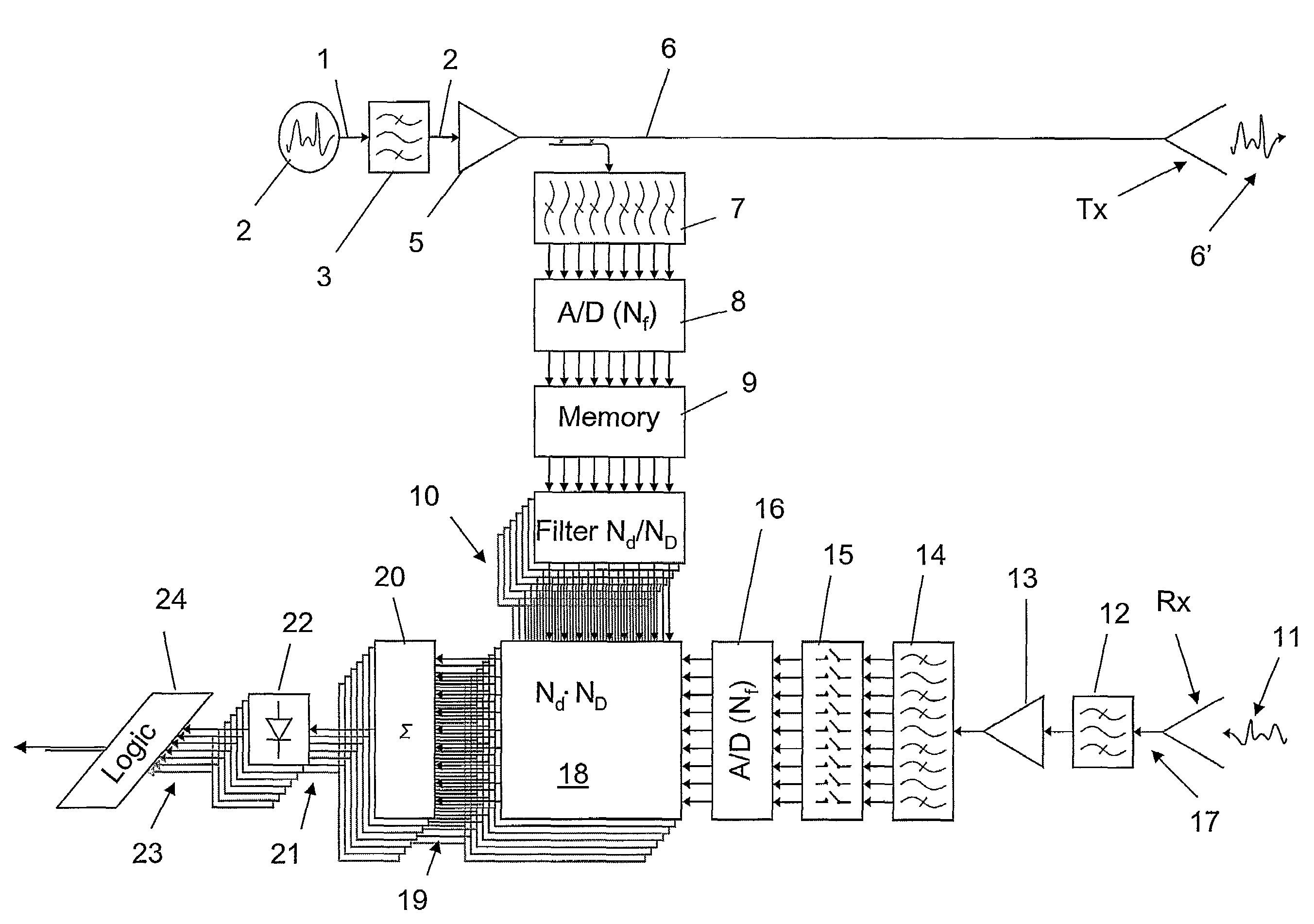
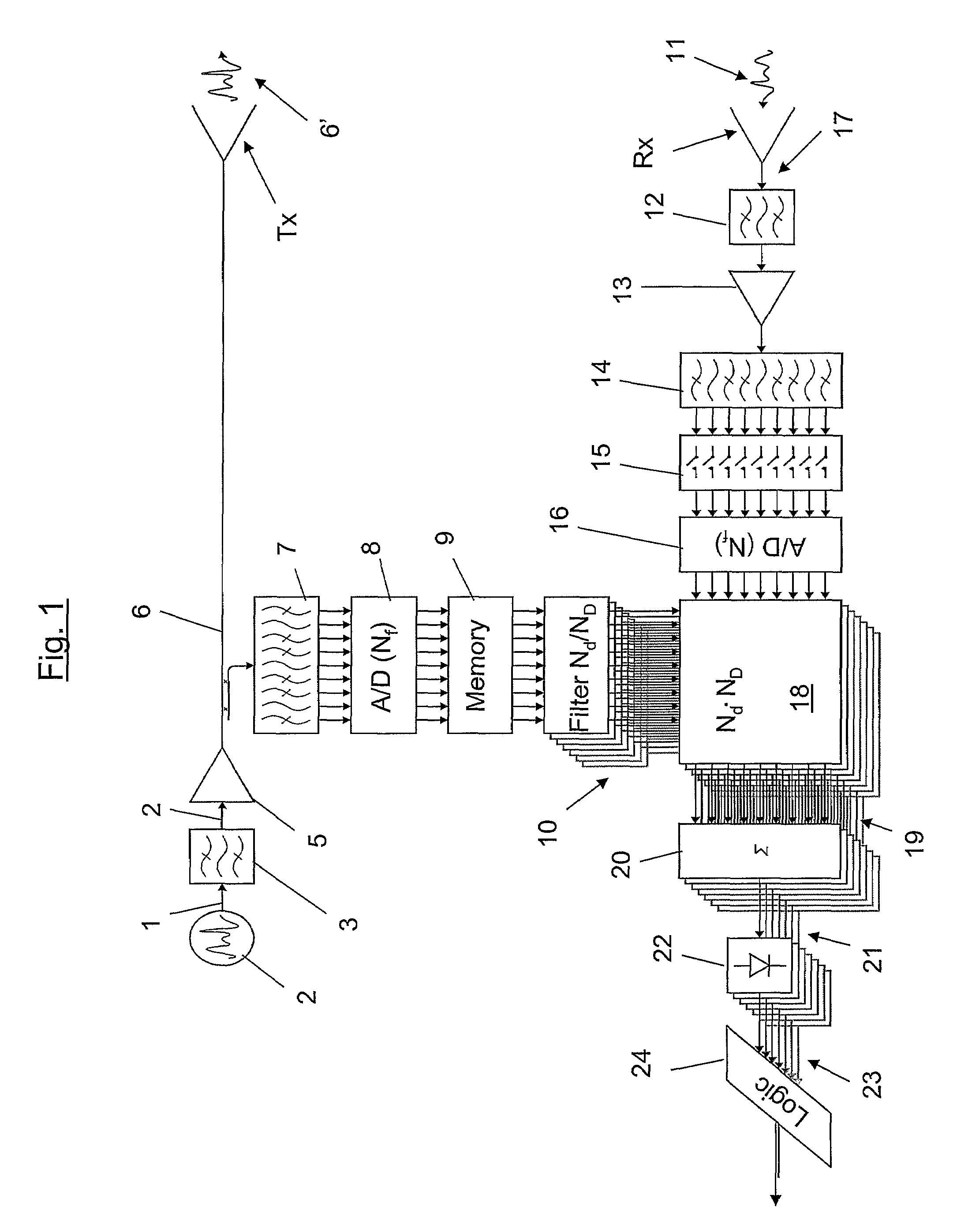
[0053]FIG. 1 schematically shows a block diagram over the method and the radar and control device according to one embodiment of the invention. A wideband signal 1, with bandwidth B, is generated in a Wideband signal generator 2. The signal 1 is then processed in a band pass filter 3 (BP-filter) in order to remove frequency contents outside a filter bank. The filtered signal 4 is then enhanced in a power amplifier 5 and the enhanced signal 6 is then transmitted 6′ via a transmitting antenna Tx.

[0054]The enhanced signal 6 is copied after the power amplifier 5 and is then frequency divided by a BP-filter bank 7 into a number of Nf frequency bands. The divided signals are then converted from analog signals into corresponding digital signals in an A / D-converter cluster 8. The A / D converted signals are stored in a Memory 9. The stored signals are then manipulated such that Nd anticipated delays and ND Doppler stretches are added to the stored signal for each number Nf of frequency bands....


PUM


Abstract

The invention refers to a method and device for wideband radar, the method comprising: —generating a wideband signal (1, 6) with a bandwidth B; —copying the wideband signal (1, 6); —transmitting the wideband signal (6′); —receiving a returned echo signal (11) from the transmitted signal (6′); —dividing the copied signal into a number, Nf, of subsequent frequency bands b; —manipulating the copied and divided signal into an anticipated signal (10) by adding a number Nd of anticipated delays and a number of ND Doppler stretches to the copied and divided signal for each Nf subsequent frequency band b; —dividing the received signal (17) into a number, Nf, of subsequent frequency bands b; —correlating corresponding frequency bands in the divided received signal (17) and the anticipated signal (10) giving NdND correlated signals (19) for determining range (R) to a target and velocity (v) of the target.

Description

TECHNICAL FIELD[0001]The invention refers to a method and device for wideband radar. The method comprises:[0002]generating a wideband signal with a bandwidth B;[0003]transmitting the wideband signal;[0004]receiving a returned echo signal from the transmitted signal, and;[0005]manipulating the stored signal for an estimate of the echo return for range and velocity.BACKGROUND ART[0006]In the field of wideband radar systems it is known that range resolution is inversely proportional to the bandwidth used for the radar. Furthermore, it is known that velocity resolution depends inversely on integration of time. A challenge in the design of broadband radar systems is to achieve velocity resolution as good as the range resolution. The range resolution is normally better than required.[0007]Problems with existing solutions are low velocity resolution compared with the range resolution. There is also a problem with a high jamming sensitivity since it is not possible to exclude jammed parts o...

Claims


Application Information

Patent Timeline
Patent Type & Authority Patents(United States)
IPC IPC(8): G01S13/58G01S13/532
CPCG01S13/0209G01S13/532
Inventor FALK, KENT
Owner TELEFON AB LM ERICSSON (PUBL)
Learn More