
Flexible water gate

a water gate and flexible technology, applied in the field of water gates, can solve the problems of significant flooding danger of the surrounding area, high construction cost, and serious disturbance of the habitat of sub-sea life forms and the surrounding environmen

Inactive Publication Date: 2008-10-14
UNIV COURT OF GLASGOW CALEDONIAN UNIV
View PDF17 Cites 5 Cited by
  • Summary
  • Abstract
  • Description
  • Claims
  • Application Information

AI Technical Summary

Benefits of technology

[0011]It is an object of the present invention to provide a flexible water gate suitable for retaining water in a port, canal or river estuary that is economical to build and maintain while providing a controllable means for deploying the gate when required.
[0012]It is a further object of the present invention to provide a flexible flood control barrier comprising one or more flexible water gates that can be controllably deployed at times when tide levels rise to produce an imminent risk of flooding of the surrounding area.
[0021]Preferably the adjustment means comprises a turn buckle adjustment screw wherein the turn buckle adjustment screw allows the tension within the support lines to be varied.

Problems solved by technology

Typically, a number of gates are located across a river estuary and are deployed at times when tide levels rise to such a point that there is a significant danger of flooding of the surrounding area.
Such structures are therefore extremely expensive and their installation can seriously disturb the habitat of the sub-sea life forms and the surrounding environment.
However, for various reasons these gate designs are prone to leakage.
In the UK alone 73% of ports that employ Mitre gates exhibit substantial levels of leakage.
Such leaks cost time and the associated water losses can render the port unattractive and ultimately inoperable.
However, Mitre gates require major maintenance work every 10 to 15 years that typically incurs costs of .English Pound.200,000.
In addition the effects of global warming are reducing the efficiency of Mitre gates due to increases in the associated water levels.
Such increased water levels act to reduce this difference hence reducing the gate efficiency.
A second disadvantage of such gate designs is the fact that they employ hardwoods in order to provide the required watertight seals.
Such civil engineering is both time consuming and expensive incurring costs of several millions of pounds.

Method used


Image

  • Flexible water gate
  • Flexible water gate
  • Flexible water gate

Examples


Embodiment Construction

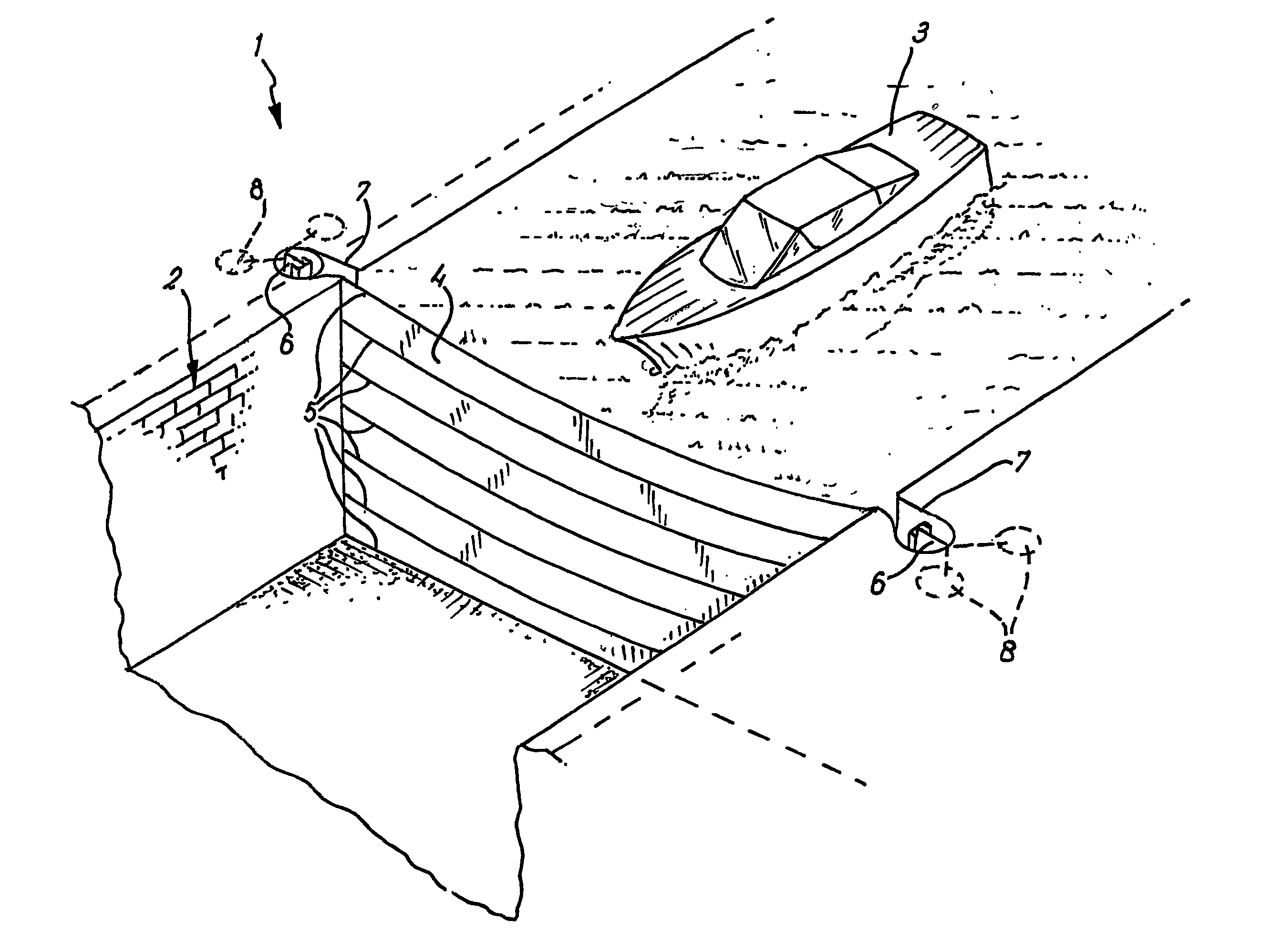
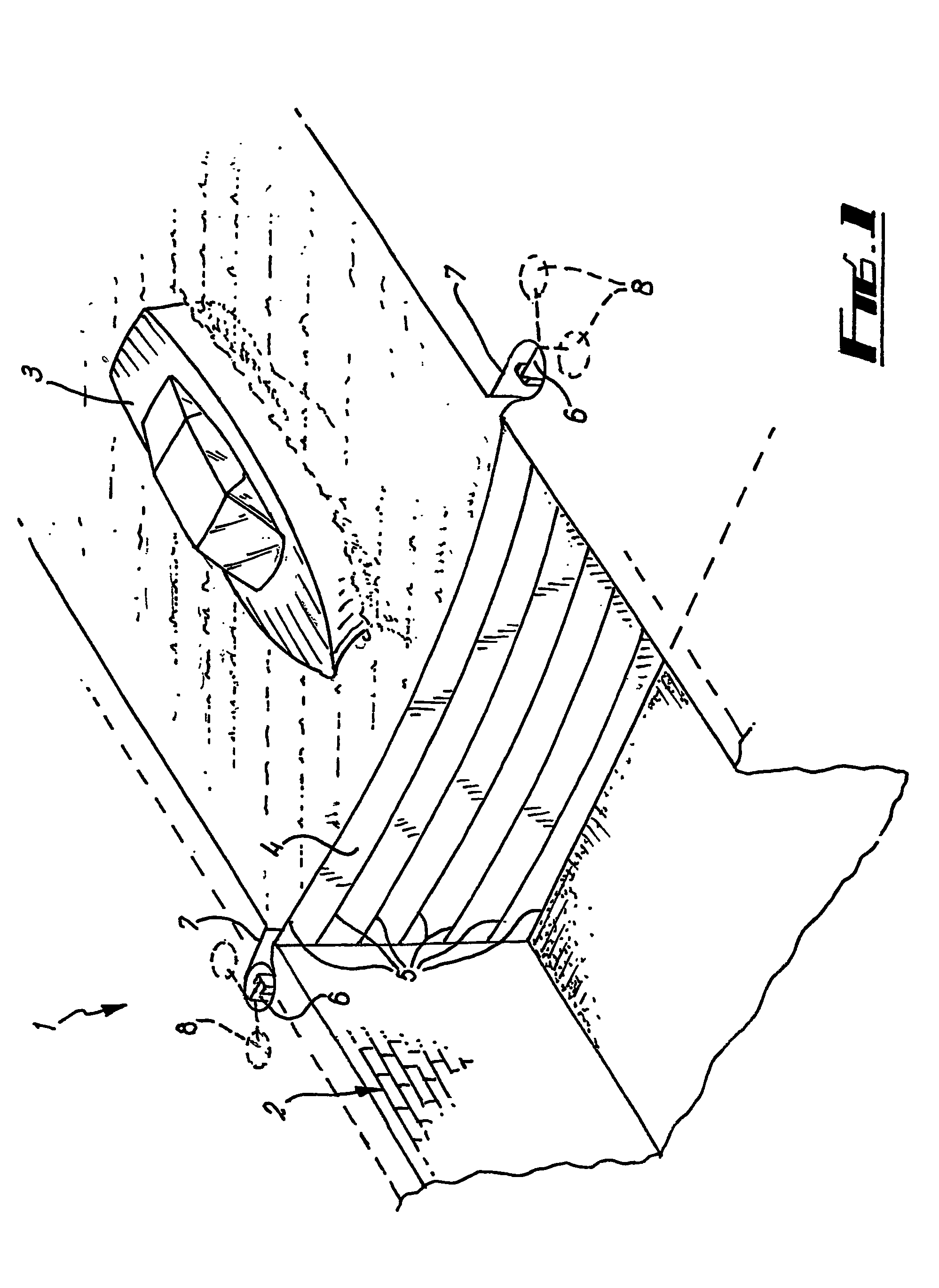
[0047]FIG. 1 presents a schematic illustration of a flexible water gate 1 incorporated with a canal system 2 containing a vessel 3. The flexible water gate 1 can be seen to comprise a flexible membrane 4 made from either Nylon or Polyester, a plurality of gate ropes 5, two support frames 6 each housed within a support frame recess 7 and two pile foundations 8 associated with each support frame 6.

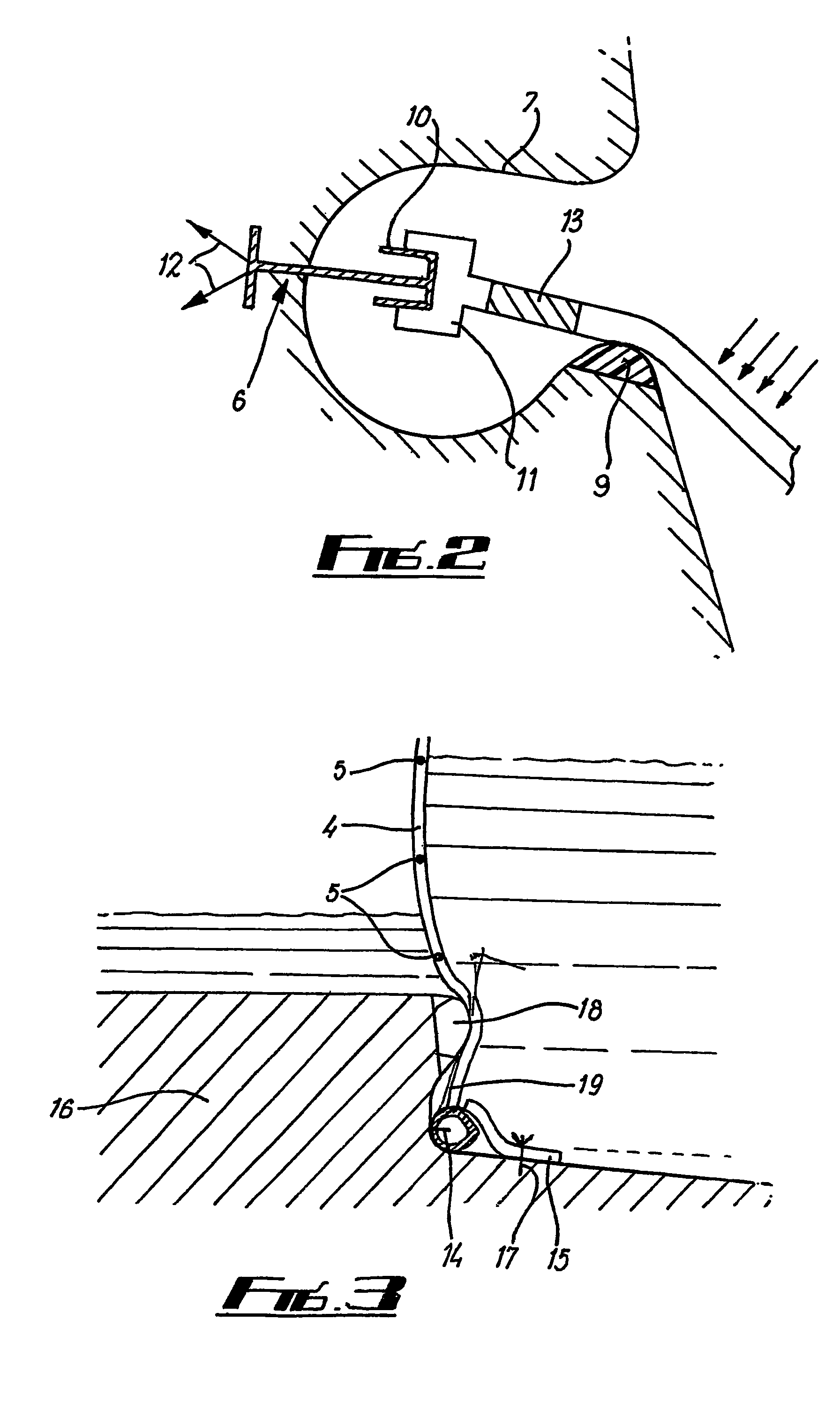
[0048]Further detail of the support frames 6 and support frame recesses 7 is presented in FIG. 2. The support frame recess 7 comprises a Neoprene seal 9 located on the low water side of the flexible water gate 1.

[0049]The support frame 6 comprises a vertical post 10, a plurality of rollers 11 mounted on the vertical post 10, two support guys 12 and a plurality of turn buckle adjustment screws 13. The flexible water gate 1 is attached to the support frame 6 via the gate ropes 5. A particular gate rope 5 connects to one end of a turn buckle adjustment screw 13. The opposite end of the turn buc...


PUM


Abstract

A flexible water gate is described that is suitable for retaining water in a port, canal or river estuary. The gate is both economical to build and maintain and comprises a gate controller that allows a flexible member to be controllably moved between a closed and open position, as required. A flexible flood control barrier that comprises one or more of the aforementioned flexible water gates is also described. These gates are deployed side to side and provide an economical way of providing flood protection to an area susceptible to flood tides. When not in use the flexible membranes of the flexible water gates can be stored on the riverbed so permitting unrestricted access for marine vessels.

Description

CROSS-REFERENCE TO RELATED APPLICATIONS[0001]This application is the national phase of International (PCT) Patent Application Serial No. PCT / GB02 / 05579, filed Dec. 9, 2002, published under PCT Article 21(2) in English, which claims priority to and the benefit of British Patent Application No. 0129435.4, filed Dec. 8, 2001, the disclosures of which are incorporated herein by reference.FIELD OF THE INVENTION[0002]The present invention relates to the field of water gates. In particular, it relates to a water gate made from a flexible membrane for use within a port, canal or river estuary.BACKGROUND OF THE INVENTION[0003]Water gates are employed in a range of impound docks, marinas and canals in order to protect vessels from the detrimental effects of tides, wind and waves. Similarly such gates are employed within lock mechanisms so as to permit vessels to move up and down from one water level to another within a canal.[0004]A further area where water gates are employed is in the constr...

Claims


Application Information

Patent Timeline
IPC IPC(8): E02B7/20E02B7/00E02B7/26
CPCE02B7/005E02B7/26
Inventor CULLEN, MARTIN
Owner UNIV COURT OF GLASGOW CALEDONIAN UNIV
Learn More