Navigation switch

a technology of navigation switch and switch body, which is applied in the field of navigation switch, can solve the problems of destroying the switching element, and the navigation switch described in the outset has no protection against excessive operating force, so as to achieve better protection against premature wear and destruction

Inactive Publication Date: 2008-10-14
CONTINENTAL AUTOMOTIVE GMBH
View PDF19 Cites 6 Cited by
  • Summary
  • Abstract
  • Description
  • Claims
  • Application Information

AI Technical Summary

Benefits of technology

[0007]It is an object of the invention to provide a navigation switch in which...

Problems solved by technology

The navigation switches described in the outset have no protection against excessive operating forces at the present time.
Improper or excessively heavy operation of the operating element produces a large operating forc...

Method used


Image

  • Navigation switch
  • Navigation switch
  • Navigation switch

Examples


Embodiment Construction

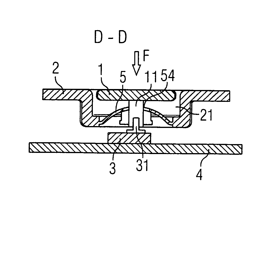
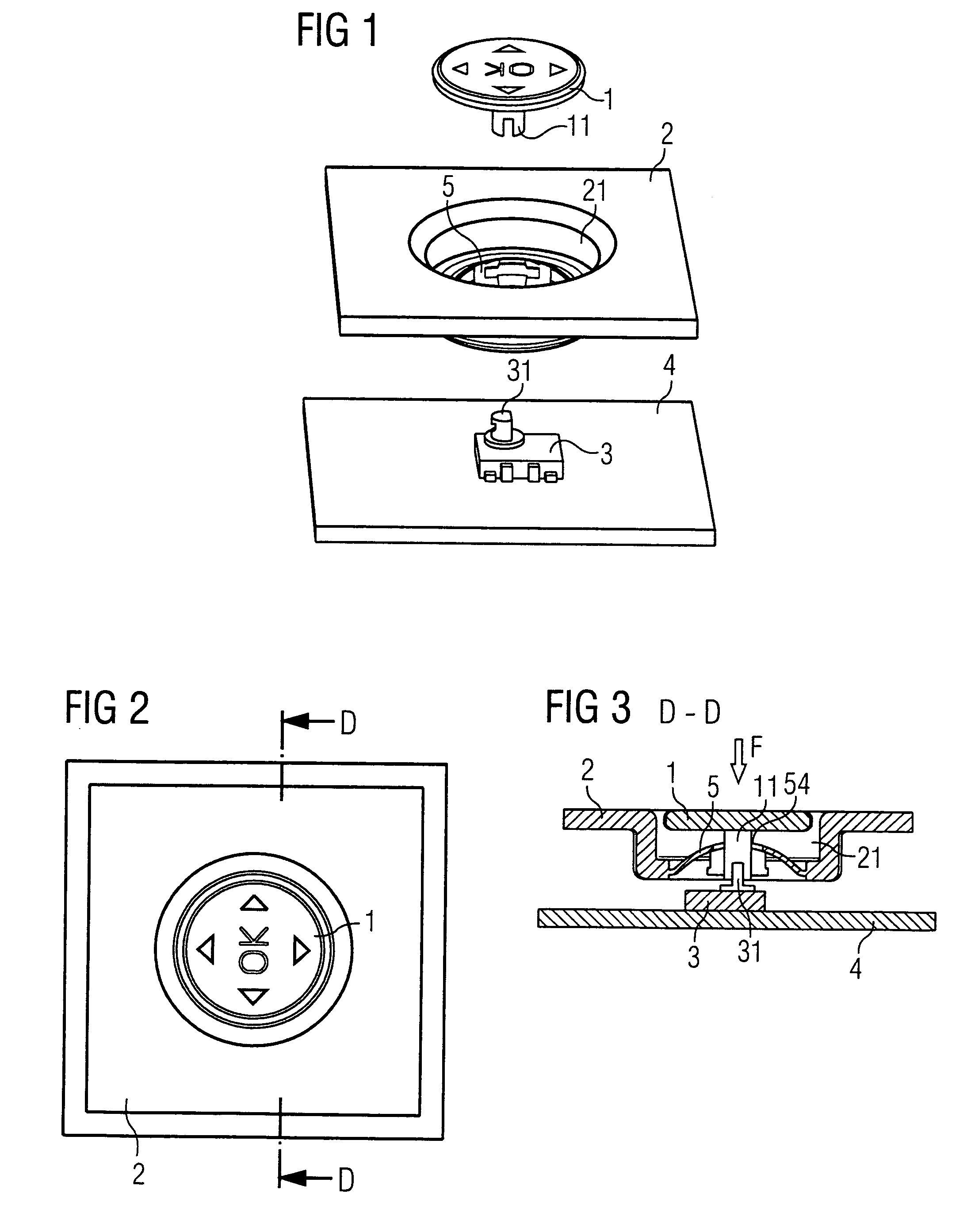
[0040]FIG. 1 shows the perspective illustration of a navigation switch based on the invention. The navigation switch has a switching element 3 with a square base area, said switching element being arranged on a housing part or on a board 4, for example. The switching element 3 has an operating arm 32 which is routed through a cutout in the cover of the switching element 3 and which serves as an axial extension to a switching lever (not shown here) arranged in the interior of the switching element 3. The switching lever arranged centrally in the interior of the switching element 3 can be moved against at least two contact regions, so that upon movement into a contact position an electrical contact is switched.

[0041]In addition, the navigation switch has a circular operating element 1 having four radially and one centrally arranged switching positions. The underside of the operating element 1 carries a tappet 11 arranged in the axial direction. In addition, the navigation switch has a...


PUM


Abstract

The present invention relates to a navigational button including an actuating element which is displaceable at least in two directions and controls the navigation button. The present actuating element is arranged in a casing and performs an action on a communication element. A limitation element is disposed between the actuating element and the casing in such a way that it limits actuation efforts performed on the navigational button.

Description

CROSS REFERENCE TO RELATED APPLICATIONS[0001]The present application is a continuation of International Application Serial Number PCT / DE03 / 03120, filed Sep. 19, 2003, which designated the United States and further claims priority to German patent application 10247093.6, filed Sep. 10, 2002, the both of which are herein incorporated by reference.BACKGROUND OF THE INVENTION[0002]The invention relates to a navigation switch having an operating element which can be tilted in at least two directions and which can be used to operate the navigation switch, a housing holding the operating element and a switching element on which the operating element acts.[0003]Navigation switches normally have a switching housing with a switching element arranged in the interior of the switching housing, said switching element being able to be moved against at least two contact regions and, when moved, reaching a contact position which switches an electrical contact. The switching element has an operating ...

Claims


Application Information

Patent Timeline
IPC IPC(8): G09G5/00H01H25/04
CPCH01H25/041H01H2221/064
Inventor BILGER, MARKUSGOTZ, JURGENRIESTER, THOMASSTEIERT, MICHAEL
Owner CONTINENTAL AUTOMOTIVE GMBH
Why Eureka
Try Eureka