
Method and system for data destruction in a phase change memory-based storage device

a phase change memory and storage device technology, applied in the field of data storage, can solve the problems of insufficient residual charge inability to overwrite all the physical cells of the pcm, and inability to achieve the effect of facilitating data destruction

Active Publication Date: 2019-03-21
ALIBABA GRP HLDG LTD
View PDF12 Cites 2 Cited by
  • Summary
  • Abstract
  • Description
  • Claims
  • Application Information

AI Technical Summary

Benefits of technology

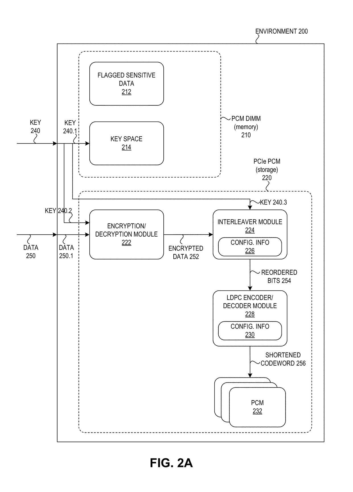
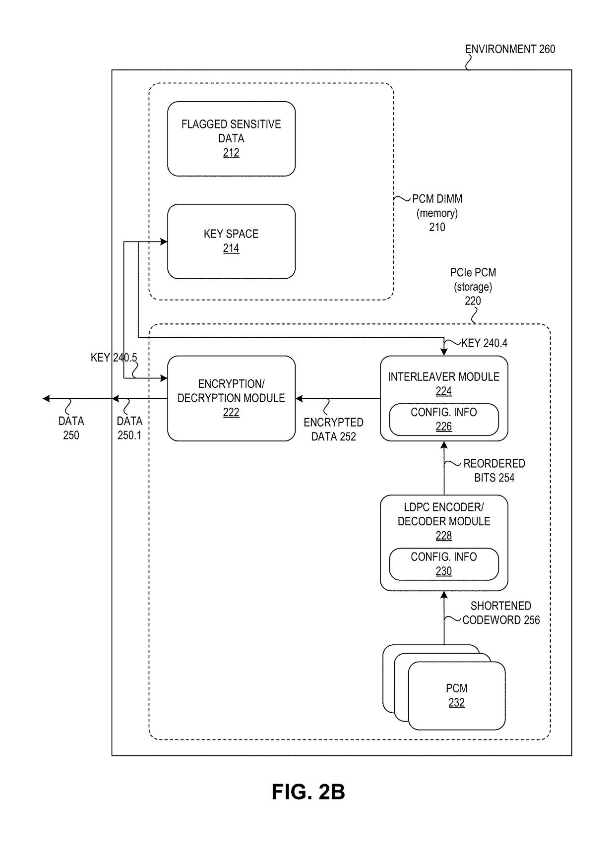
The patent describes a system and device for securely destroying data stored in a phase change memory-based storage device. When a power loss is detected, the system or device overwrites keys and configuration information used to transform data, preventing the data from being recovered. Additionally, the system or device includes an encryption module to encrypt data based on a key, an interleaver module to reorder the data, and an encoder module to encode the data to obtain a code, which is stored in a separate phase change memory to further prevent the data from being recovered. The technical effects include improved security and protection of data stored in a phase change memory-based storage device.

Problems solved by technology

The data stored in the PCM may include sensitive information, which can be vulnerable to unwanted access after a power loss.
However, because the PCM can have a high density and a high capacity (e.g., 4 terabytes), it is neither feasible nor efficient to overwrite all the physical cells of the PCM.
For example, after a power loss, there may be an insufficient amount of residual charge to overwrite all the cells of the PCM.
Furthermore, making the stored data permanently unrecoverable after a power loss may not be a desired strategy for managing the system.
Thus, while PCM provides benefits including both an access speed greater than NAND flash and a storage capacity greater than DRAM, the issue of efficient data destruction to protect sensitive data after a power loss remains unsolved.
During operation, the system detects, by the storage device, a power loss.
Subsequent to the power loss, the system overwrites keys and configuration information used to transform data stored in the phase change memory, wherein the keys and the configuration information are stored in the phase change memory, thereby preventing the data from being recovered.

Method used


Image

  • Method and system for data destruction in a phase change memory-based storage device
  • Method and system for data destruction in a phase change memory-based storage device
  • Method and system for data destruction in a phase change memory-based storage device

Examples


Embodiment Construction

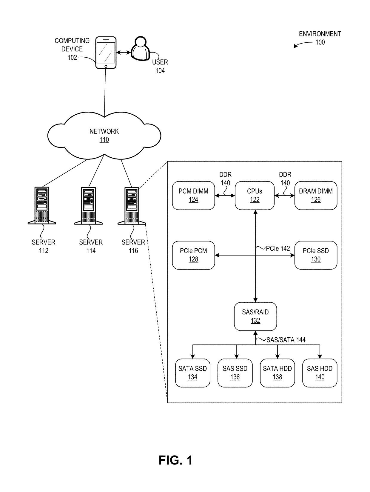
[0024]The following description is presented to enable any person skilled in the art to make and use the embodiments, and is provided in the context of a particular application and its requirements. Various modifications to the disclosed embodiments will be readily apparent to those skilled in the art, and the general principles defined herein may be applied to other embodiments and applications without departing from the spirit and scope of the present disclosure. Thus, the embodiments described herein are not limited to the embodiments shown, but are to be accorded the widest scope consistent with the principles and features disclosed herein.

[0025]Overview

[0026]The embodiments described herein solve the problem of protecting the recovery of data in a PCM-based storage device after a power loss by providing a system which uses residual power to overwrite a small portion of specific data in the PCM, thus avoiding the need to overwrite all the data stored in the PCM.

[0027]DRAM DIMM i...


PUM


Abstract

One embodiment facilitates data destruction in a phase change memory-based storage device. During operation, the system detects, by the storage device, a power loss. Subsequent to the power loss, the system overwrites keys and configuration information used to transform data stored in the phase change memory, wherein the keys and the configuration information are stored in the phase change memory, thereby preventing the data from being recovered.

Description

BACKGROUNDField[0001]This disclosure is generally related to the field of data storage. More specifically, this disclosure is related to a method and system for facilitating data destruction in a phase change memory-based storage device.Related Art[0002]The proliferation of the Internet and e-commerce continues to create a vast amount of digital content. Various storage systems have been created to access and store such digital content. One such storage system uses phase change memory (PCM), which is a type of non-volatile random access memory. PCM uses a specific type of glass and can hold multiple bits in a single cell (or sector). PCM is faster than NAND flash, and has a higher density than conventional dynamic random access memory (DRAM). PCM has a low read / write latency, and may be used for fast persistent data storage. In contrast with a DRAM Dual In-line Memory Module (DIMM) (which loses its data after a power loss), PCM, as a non-volatile memory, retains its stored data even...

Claims


Application Information

Patent Timeline
IPC IPC(8): G06F21/60G11C13/00G06F3/06G06F11/10G11C29/52H04L9/08H04L9/14
CPCG06F21/602G11C13/0004G11C13/0097G06F3/0623G06F3/064G06F3/0652G06F3/0679G06F11/1068G11C29/52H04L9/0894H04L9/14G11C5/144G11C7/1006G11C13/0038G11C13/0059G11C13/0069G06F11/1076G11C7/24G11C2029/0411H04L2209/34G06F2221/2143G06F21/755G06F3/0688
Inventor LI, SHUZHOU, PING
Owner ALIBABA GRP HLDG LTD
Learn More