Systems and methods for supplying a distributed light source

a distributed light source and distribution system technology, applied in the direction of fibre light guides, planar/plate-like light guides, instruments, etc., can solve the problems of poor directionality, poor efficiency and thermal problems, and low intensity

Inactive Publication Date: 2008-10-14
PRINCETON LIGHTWAVE INC
View PDF8 Cites 21 Cited by
  • Summary
  • Abstract
  • Description
  • Claims
  • Application Information

AI Technical Summary

Benefits of technology

[0017]In another embodiment of the present invention, a linear field radiant electromagnet energy transmitting apparatus is provided and may include at least one length of optical fiber including a core having a diffraction grating for diffracting electromagnetic energy in a predetermined direction and a convex surface having a length corresponding to the length of optical fiber and positioned at a predetermined distance from the optical fiber in a direction to receive electromagnetic energy diffracted by the grating of the optical fiber thereby establishing a linear lighting field.

Problems solved by technology

While the sources for such a system are low cost, they suffer from low intensity, poor directionality, poor efficiency and thermal problems. FIG. 1B illustrates an array of bright LEDs 104 used to create a line source.
However, since such a large number of sources are required to create a uniform power density, the cost and complication of the resulting system is typically prohibitive.
While these scatter based methods can create uniform illumination, each system is generally inefficient and the resulting light field lacks directionality.
This approach is costly and exposes operators to free space laser power (U.S. Pat. No. 6,864,970).

Method used


Image

  • Systems and methods for supplying a distributed light source
  • Systems and methods for supplying a distributed light source
  • Systems and methods for supplying a distributed light source

Examples


Embodiment Construction

[0052]Some embodiments of the invention may be designed for use with near infrared light from a single source, while other embodiments may be designed for operation at wavelengths spanning portions of the visible and near infrared.

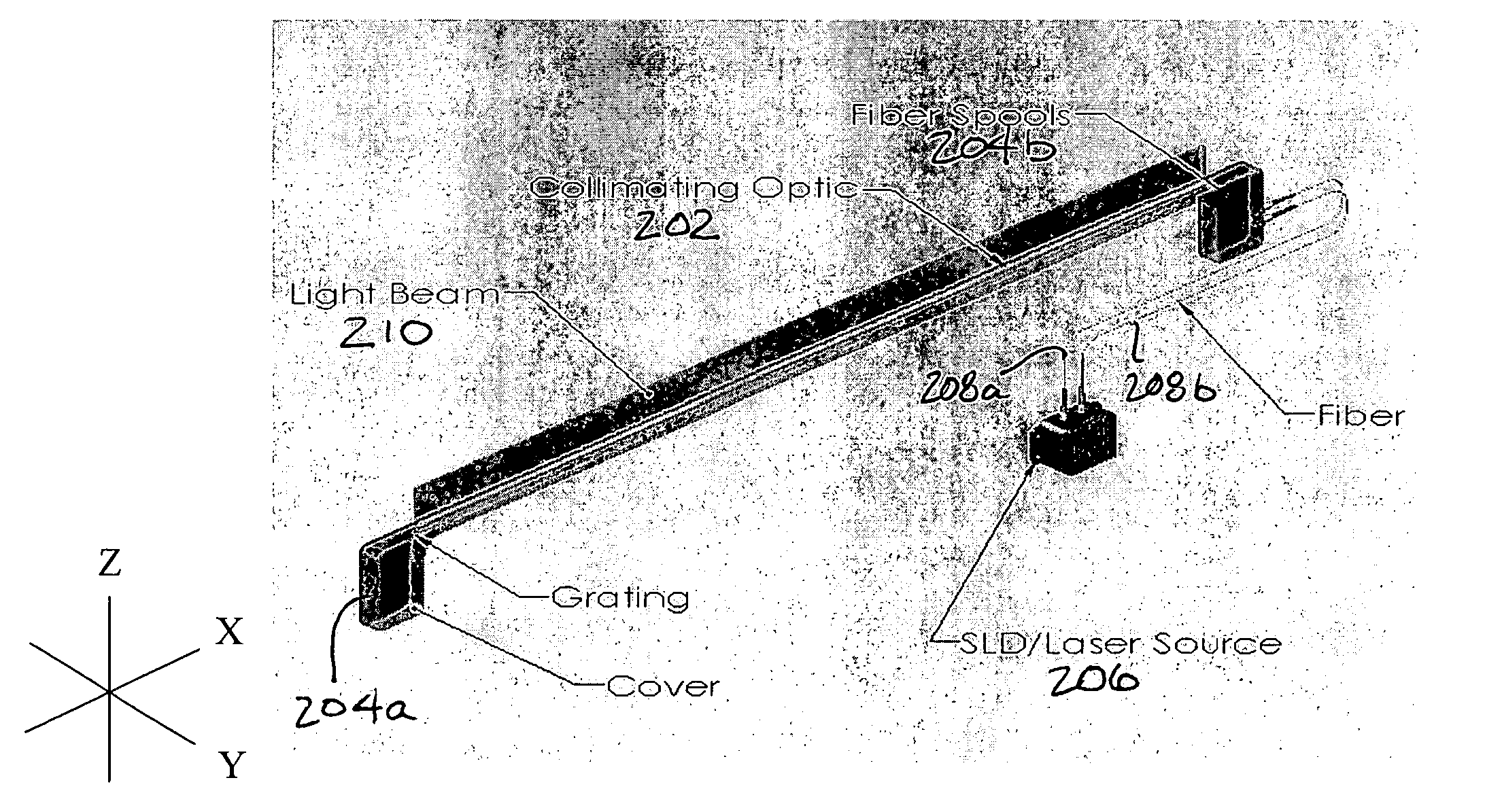
[0053]FIGS. 2A-2B illustrate an exemplary linear light field system according to the present invention. As shown, system 200 includes an optical element 202 (a cylindrical convex optical surface) having an optical fiber with a blazed internal grating (e.g., see reference numeral 302 in FIG. 3A) positioned adjacent the optical element 202 and optical fiber spools 204a and 204b (only a single spool of optical fiber may be used in some embodiments). A light source, laser 206, provides (pumps) laser light into the optical element via the optical fibers 208a and 208b, to produce a linear light source field 210.

[0054]Embodiments of the present invention may include several types of light sources (i.e., light emitting devices) may be coupled to the optical fiber,...


PUM


Abstract

Embodiments of the present invention are directed methods, apparatuses and system for establishing a linear radiant electromagnet energy field. In one embodiment of the invention, a system for providing a linear field of electromagnetic energy includes a laser, at least one length of single mode or multimode optical fiber including a core having a stitched diffraction grating of predetermined pitch for diffracting electromagnetic energy in a predetermined direction, a longitudinal optical element having a convex surface and a length corresponding to the length of optical fiber, wherein the optical element is sized such that the convex surface is positioned at a predetermined distance from the optical fiber and in a direction to receive electromagnetic energy diffracted by the grating of the optical fiber thereby establishing a linear lighting field and a lenticular array.

Description

CLAIM TO PRIORITY[0001]The present application claims priority to 35 U.S.C. §119(e) of U.S. provisional patent application No. 60 / 688,488, filed Jun. 7, 2005, the entire disclosure of which is incorporated herein by reference.FIELD OF THE INVENTION[0002]The present invention is directed to the emission of radiant electromagnetic energy from optical wave guides, and more particularly to lighting arrangements for distributing a predetermined power density over a rectangular region.BACKGROUND OF THE INVENTION[0003]Lighting arrangements that distribute power density over a long rectangular region are used for high speed sorting and testing of various products, including foodstuffs, vegetables, paper, pharmaceauticals, plastics, recyclables, and the like. These systems illuminate a moving sheet of product so that the product may be inspected with cameras or spectroscopic instruments (see, for example: http: / / www.satake-usa.com, http: / / www.bestnv.com / , and http: / / www.buhlergroup.com / 17217...

Claims


Application Information

Patent Timeline
Patent Type & Authority Patents(United States)
IPC IPC(8): G02B6/34
CPCG02B6/0006G02B6/001G02B6/002G02B6/0028G02B6/02057G02B6/02085G02B6/42
Inventor CARVER, GARY E.SWANSON, ALKAGARBUZOV, DMITRIKOCH, TIMOTHY R.
Owner PRINCETON LIGHTWAVE INC
Why Eureka
Try Eureka