Lock device

a technology of locking device and lock rod, which is applied in the direction of padlocks, building locks, constructions, etc., can solve the problems of shaking of the lock rod, difficult operation, unstable condition, etc., and achieve the effect of convenient storage and portability

Inactive Publication Date: 2008-10-21
SU WEN CHUN
View PDF13 Cites 35 Cited by
  • Summary
  • Abstract
  • Description
  • Claims
  • Application Information

AI Technical Summary

Benefits of technology

[0013]Preferably, said lock head is provided with a bolt at the top of said lock head to secure said connecting rod of said lock shaft unit with said lock case and said anti-dust cover, allowing said connecting rod to rotate in 360 degrees with respect to said lock case and said anti-dust cover.
[0023]It is another object of the present invention to provide a lock device, which comprises an anti-dust cover and a cap to protect the lock device from dust.
[0024]It is a further object of the present invention to provide a lock device, which provides a lock shaft unit having a flat body and is easy to store and to carry.
[0025]It is still a further object of the present invention to provide a lock device, which uses a second trough and a third trough to support the lock shaft unit to prevent the lock device from looseness in a locked position.

Problems solved by technology

However, when the engaging block is inserted into the engaging hole, the engaging block will be supported only by the engaging hole, which is not strong enough to hold the engaging rod, thus the rod is shaking and in a unstable condition with the lock head.
Furthermore, the lock shaft unit and the lock head can not rotate 360 degrees with each other, which causes the operation difficult.

Method used


Image

  • Lock device
  • Lock device
  • Lock device

Examples


Embodiment Construction

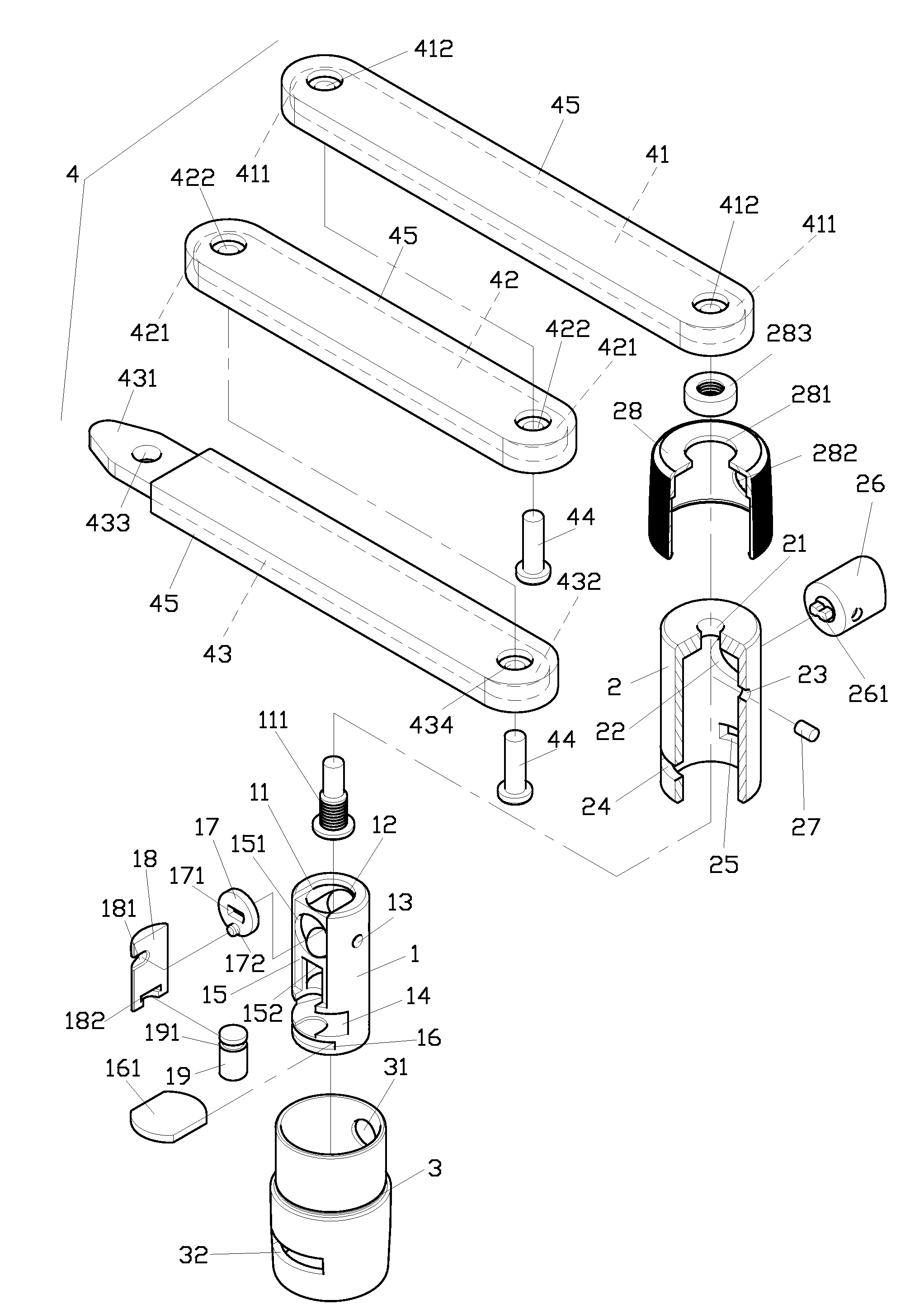
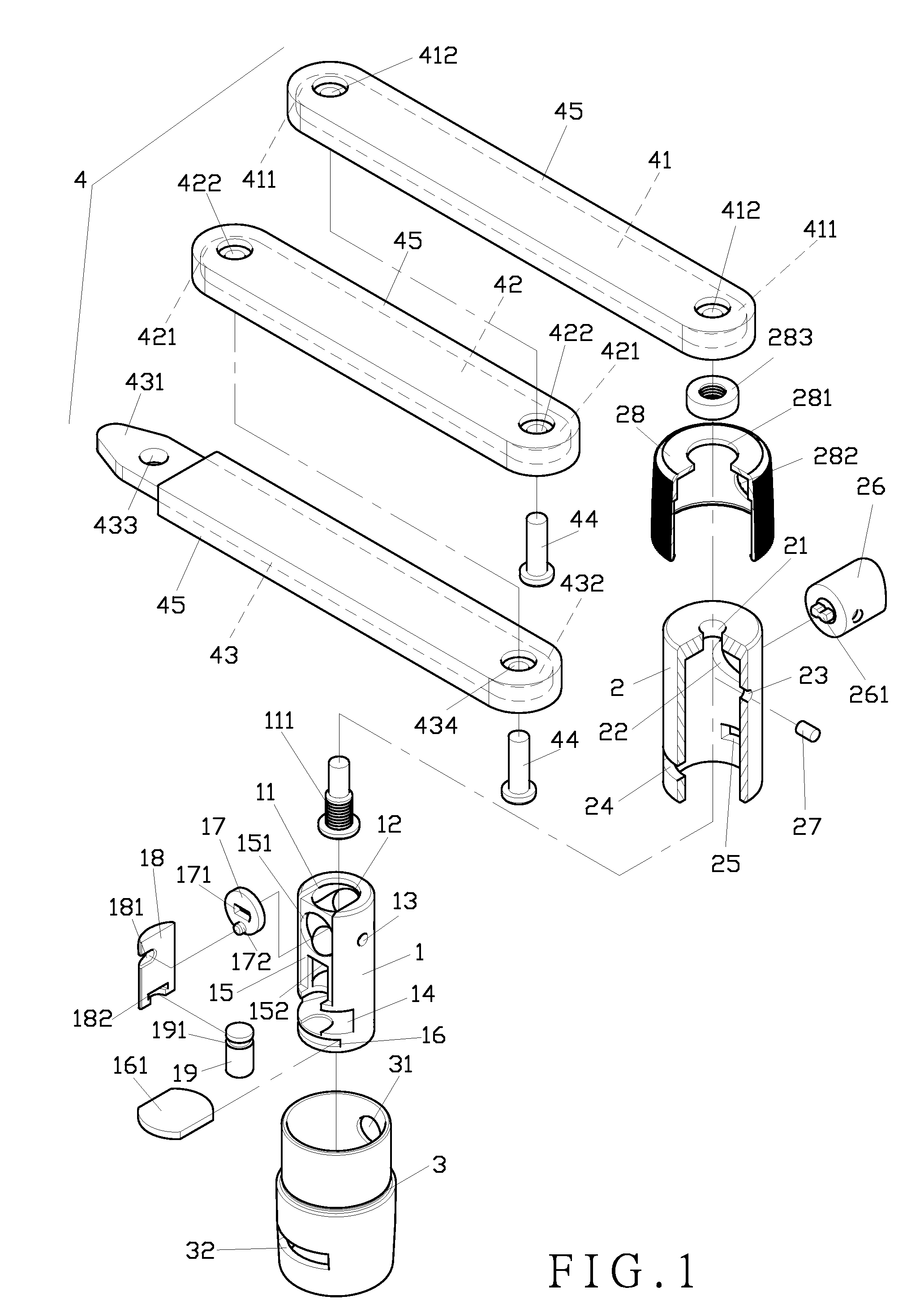
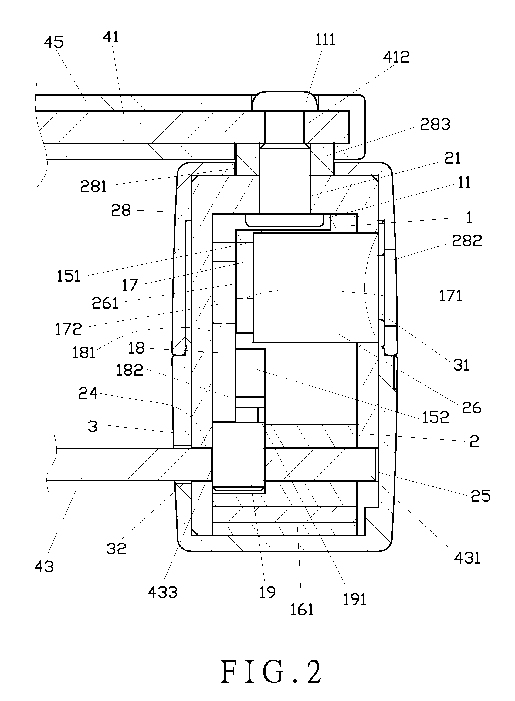
[0035]As shown in FIG. 1, a preferred embodiment of the present invention comprises a lock head 1, a lock case 2, a cap 3 and a lock shaft unit 4.

[0036]The lock head 1 comprises a first through hole 11 at the top thereof, a first insertion hole 12, a first securing hole 13, a first trough 14, a groove 15, and a first tray 16 on the circumference of the lock head 1. A hole 151 and a slot 152 are formed in the groove 15 for insertion of a linking shaft 17, a sliding plate 18 and a latch 19. The linking shaft 17 comprises an insertion hole 171 and a protuberance172. The sliding plate 18 has a linking slot 181 and a connecting trough 182. The linking slot 181 of the sliding plate 18 is adapted to receive the protuberance 172 of the linking shaft 17 therein. The latch 19 has a circular trough 191 adapted to connect with the connecting trough 182 of the sliding plate 18. The latch 19 is disposed in the first trough 14. The first tray 16 is to receive a plate 161 therein. The first through...


PUM


Abstract

A lock device includes a lock head, a lock case, a cap, and a lock shaft unit. The lock head is inserted into the lock case. The lock case is provided with an anti-dust cover which is rotatable with respect to the cap. The lock shaft unit is pivotally connected to the lock case, allowing the lock shaft unit to rotate in 360 degrees with respect to the lock case.

Description

BACKGROUND OF THE INVENTION[0001]1. Field of the Invention[0002]The present invention relates to a lock device, and more particularly to one that comprises a lock head, a lock case provided with a cap and an anti-dust cover which are rotatable with each other, and a lock shaft unit pivoted to the lock case so as to rotate in 360 degrees with each other.[0003]2. Description of the Prior Art[0004]A conventional lock device comprises a lock shaft unit and a lock head. The lock shaft unit comprises an engaging rod with an engaging block at one end and a connecting rod at the other end. The lock head comprises a lock core, an engaging hole and a connecting hole thereon for connection of the engaging rod and the connecting rod respectively.[0005]However, when the engaging block is inserted into the engaging hole, the engaging block will be supported only by the engaging hole, which is not strong enough to hold the engaging rod, thus the rod is shaking and in a unstable condition with the ...

Claims


Application Information

Patent Timeline
Patent Type & Authority Patents(United States)
IPC IPC(8): E05B73/00E05B17/14
CPCE05B67/003E05B17/002Y10T70/40Y10T70/409Y10T70/498Y10T70/70Y10T70/7955Y10T70/8649
Inventor SU, WEN-CHUN
Owner SU WEN CHUN
Why Eureka
Try Eureka