Carrying vehicle, manufacturing apparatus, and carrying system

a manufacturing apparatus and carrying system technology, applied in the direction of filter regeneration, dispersed particle filtration, combinatorial devices, etc., can solve the problems of large-capacity clean room, high cost, and immediate decrease in yield, so as to prevent dust from entering the article storage, improve the carrying efficiency, and prevent the effect of dus

Inactive Publication Date: 2006-03-21
MURATA MASCH LTD
View PDF13 Cites 33 Cited by
  • Summary
  • Abstract
  • Description
  • Claims
  • Application Information

AI Technical Summary

Benefits of technology

[0059]The carrying vehicle further comprises second air injecting means for injecting air from an upper edge of the article delivery port, the air forming a down flow. With such a configuration, the second air injecting means can be driven to inject clean air against the outer surfaces of doors to remove dust attached to the outer surfaces. Therefore, by driving the second air injecting means before the doors are opened, it is possible to prevent dust attached to the outer surfaces of the doors from entering an article storage. Further, by driving the second air injecting means when the doors are opened, an air curtain can be formed which closes the article delivery port. Consequently, even when the article delivery port is open, it is possible to prevent dust from entering the article storage.
[0060]There is provided a carrying system comprising a carrying vehicle including an article storage having an article delivery port through which an article is delivered or received and stations arranged along a running path for the carrying vehicle and each provided with an article storage having an article delivery port which is opened and closed using first doors to deliver or receive an article to or from the carrying vehicle, and wherein each of the stations has wall members formed in front of and behind the article delivery port of the station in a direction in which the carrying vehicle advances, and the carrying vehicle has air injecting means arranged around the periphery of the article delivery port of the carrying vehicle to inject air to the station so as to form an air curtain. With such a configuration, the station can use the first doors to prevent dust from entering the article storage. The carrying vehicle can use the air curtain formed by the air injecting means to prevent dust from entering the article storage. Then, the formation of the air curtain prevents dust from entering the storage while the carrying vehicle is running, whether or not the storage has doors. Further, dust attached to the first doors of the station can be removed by moving the carrying vehicle to stop it at the station. The stoppage of the carrying vehicle at the station serves to clean a transfer path formed between both article delivery ports. This in turn prevents dust from being attached to the article. As a result, it is possible to prepare for a transfer to or from the carrying vehicle before the carrying vehicle arrives at the station. Further, the first doors can be opened when the carrying vehicle arrives. This improves carrying efficiency and prevents dust from being attached to the article during a transfer. Furthermore, the formation of the walls leads to the formation of a small space between the carrying vehicle and the walls. Then, it is only this space that must be cleaned. An air curtain can thus be reliably formed. As a result, dust can be more surely prevented from entering the article storage of the carrying vehicle. Further, dust can be more reliably prevented from being attached to the article during a transfer.
[0061]Second doors that can be opened and closed are arranged in the article delivery port of the carrying vehicle, and the first and second doors are controlled so that the doors start to be opened before the carrying vehicle arrives at a stopped position at the station and are completely closed after the carrying vehicle has left the stopped position, with an opening of the first doors being located within the air curtain after the first doors have started to be opened and before the first doors are completely closed. With such a configuration, the carrying vehicle is provided with the second doors. Accordingly, when the doors are closed, operation of each air injecting means can be stopped. As a result, the power consumption of the carrying vehicle can be reduced. Further, the first and second doors start to be opened before the carrying vehicle stops at the station and are closed after the carrying vehicle leaves the station. Consequently, production efficiency can be further improved. Furthermore, the opening of the first doors arranged in the station is always within the air curtain. Therefore, even if the first doors of the carrying vehicle are opened or closed while the carrying vehicle is moving, dust is prevented from entering the article storage of the station.

Problems solved by technology

Consequently, the attachment of foreign matter (e.g. dust particulate) to the substrate during manufacture may result in an immediate decrease in yield.
However, to keep the whole production line very clean, a large-capacity clean room is required which comprises a large number of cleaning units.
High costs are thus required to build a clean room.
Further, a cleaning unit composed of a blowing fan, an HEPA (high efficiency particulate air) filter, and others requires high power to drive the blowing fan, thus requiring high running costs.
It has been difficult to maintain and manage such flow control.
However, with the method of making the space on the passage on which semiconductor device being manufactured are carried cleaner than the other spaces, when the automated carrying vehicle 1 runs, it may stir up foreign matter on a floor surface.
This makes it necessary to blow a stronger down flow against the passage, change the shape of partitioning walls around the periphery of passage, or possibly reduce the speed of the carrying vehicle.
Further, when the automated carrying vehicle 1 runs, it may stir up foreign matter on the floor surface.
Thus, if an attempt is made to increase the running speed of the automated carrying vehicle 1 in order to improve productivity, the contamination of vicinity of the transfer ports may produce more marked adverse effects.
This may lead to a decrease in yield.

Method used


Image

  • Carrying vehicle, manufacturing apparatus, and carrying system
  • Carrying vehicle, manufacturing apparatus, and carrying system
  • Carrying vehicle, manufacturing apparatus, and carrying system

Examples


embodiment 2

[0122]In Embodiment 1, description has been given of the example in which the air injecting section is provided on the entire surface of the transfer port of the automated carrying vehicle. However, in the present embodiment, a description will be given of a case in which the air injecting section is formed closer to the advancing direction than to the transfer port. Further, a description will be given of a case in which the air injecting section forms an air curtain spreading in a vertical direction.

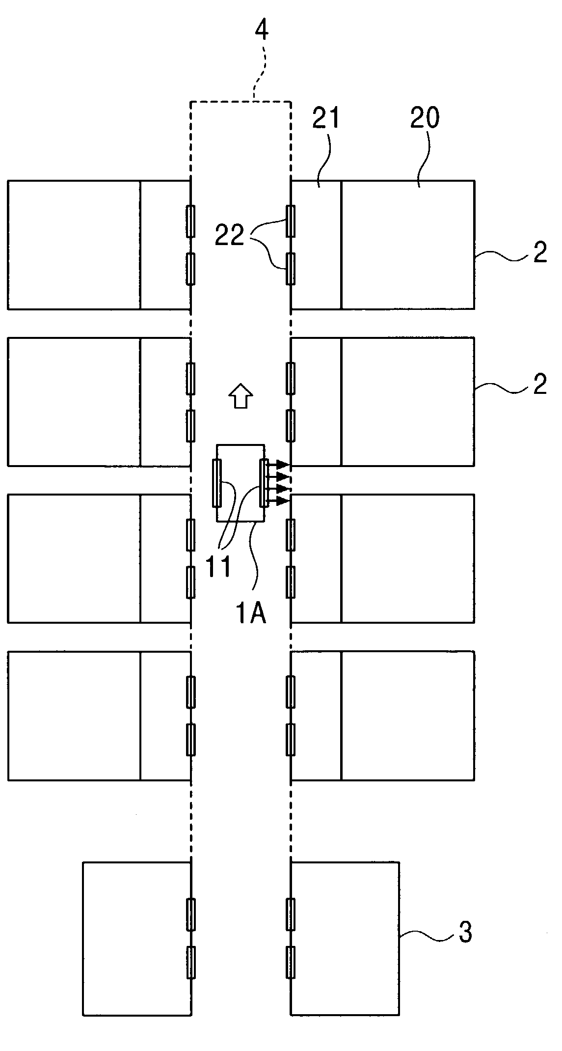
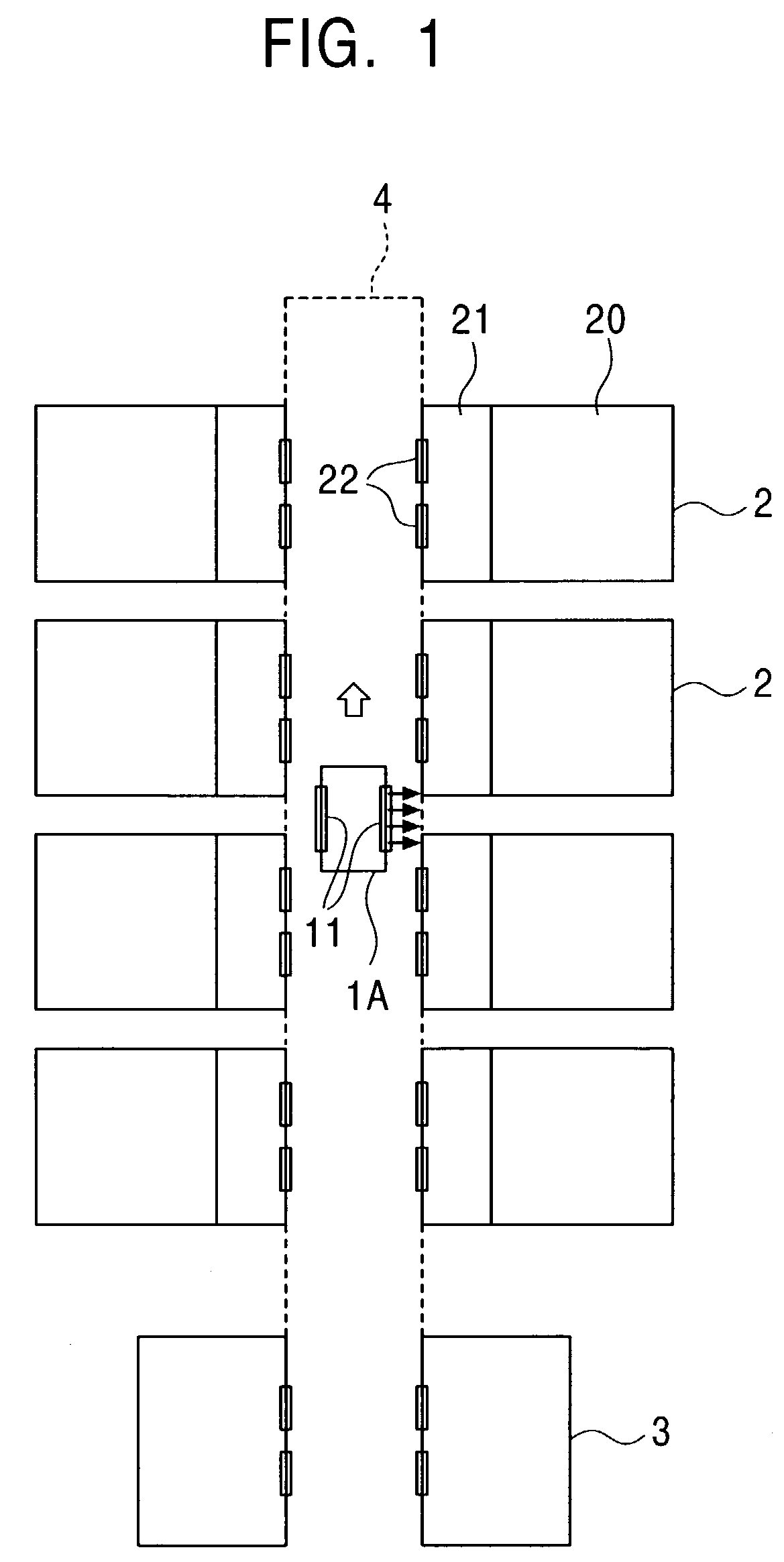
[0123]FIG. 7 is a schematic view showing an example of a configuration of an automated carrying system according to Embodiment 2 of the present invention. In the figure, 1B is the automated carrying vehicle, 2 is the semiconductor manufacturing apparatus, 3 is the stocker, and 4 is the carrying path. Further, 18B is the air nozzle, 19B is the air injecting section, 20 is the processing section, 21 is the loader / unloader, and 11 and 22 are the transfer ports.

[0124]The air injecting sect...

embodiment 3

[0132]In Embodiments 1 and 2, a description has been given of the example in which the air injecting section is provided on the side of the automated carrying vehicle. However, in the present embodiment, a description will be given of a case in which the air injecting section is provided in a corner of the automated carrying vehicle. Further, a description will be given of a case in which the air injecting section blows out air from the side of the automated carrying vehicle 1A in a direction closer to the advancing direction than to the direction normal to this side.

[0133]FIG. 9 is a schematic view showing an example of a configuration of an automated carrying system according to Embodiment 3 of the present invention. In the figure, 1C is the automated carrying vehicle, 2 is the semiconductor manufacturing apparatus, 3 is the stocker, 4 is the carrying path, and 18C is the air nozzle. Further, 19C is the air injecting section, 20 is the processing section, 21 is the loader / unloader...

embodiment 4

[0140]In the above embodiments, a description has been given of the example in which the automated carrying vehicle is provided with the air injecting section to remove foreign matter or the like attached to the transfer port of the semiconductor manufacturing apparatus. However, in the present embodiment, a description will be given of a case in which the air injecting section is provided on the semiconductor manufacturing apparatus 2 to remove foreign matter or the like attached to the transfer port 22 of the semiconductor manufacturing apparatus 2.

[0141]FIG. 11 is a sectional view schematically showing the structure of a semiconductor manufacturing apparatus 2A according to Embodiment 4 of the present invention. In this figure, the semiconductor manufacturing apparatus 2A, applied to an automated carrying system similar to that in FIG. 1, is viewed from its side. In the figure, 17 is the cassette, 20 is the processing section, 21 is the loader / unloader, the 22 is the transfer por...


PUM

PropertyMeasurementUnit
heightsaaaaaaaaaa
pressureaaaaaaaaaa
heightaaaaaaaaaa

Abstract

According to the present invention, in a carrying system comprising a carrying vehicle and a manufacturing apparatus the interior of which is kept cleaner than a surrounding environment, manufactured articles to be transferred are prevented from being contaminated by foreign matter or the like attached to transfer ports. A carrying vehicle includes a running unit 14 that runs along a predetermined carrying path, a cleaning unit 12 that supplies cleaned air, a housing section 13 to which the cleaned air is supplied and in which manufactured articles are housed, a transfer port 11 which is formed in a side of a housing and through which a manufactured article is loaded into or unloaded from the housing section 13, and an air injecting section 19A that blows out air toward the transfer port 11.

Description

FIELD OF THE INVENTION[0001]The present invention relates to a carrying vehicle, a manufacturing apparatus, and a carrying system, and more specifically, to improvements in a carrying vehicle, a manufacturing apparatus, and a carrying system which are suitable for locally cleaning a production line that desirably maintains manufactured articles in a cleaned atmosphere, e.g. a production line for liquid crystal display devices, PDPs (Plasma Display Panels), organic EL (Electro Luminescence) displays, or other semiconductor devices.BACKGROUND OF THE INVENTION[0002]In the manufacture of semiconductor devices, a substrate composed of an Si (Silicone) wafer, a planar glass, or the like is processed so as to have features of the order of microns or less. Consequently, the attachment of foreign matter (e.g. dust particulate) to the substrate during manufacture may result in an immediate decrease in yield. Thus, a conventional production line for semiconductor devices is wholly installed in...

Claims


Application Information

Patent Timeline
Patent Type & Authority Patents(United States)
IPC IPC(8): B01D46/10B65B1/04H01L21/68B01D50/00H01L21/00H01L21/677
CPCB01D50/00H01L21/67017H01L21/67724H01L21/67736Y10S55/29Y10S55/18Y10S55/46H01L21/68
Inventor ISHIHARA, HIROYUKISHIMIZU, TAKAONAKAO, TAKASHITAHARA, RYOSUKETAKEUCHI, HIDETOSHI
Owner MURATA MASCH LTD
Why Eureka
Try Eureka