Floating caliper disc brake

a technology of caliper disc brake and caliper plate, which is applied in the direction of braking elements, slack adjusters, braking members, etc., can solve the problems of increasing production costs, and achieve the effect of reducing troublesome machining work, being easy to use, and being convenient to us

Inactive Publication Date: 2008-10-21
AKEBONO BRAKE IND CO LTD
View PDF19 Cites 16 Cited by
  • Summary
  • Abstract
  • Description
  • Claims
  • Application Information

AI Technical Summary

Benefits of technology

[0012]One or more embodiments of the present invention provide a floating caliper disc brake having an inexpensive and light construction and which can reduce the troublesome machining work.
[0019]In the case of the floating caliper disc brake configured as has been described above, the caliper is disposed between the arm portions provided on the support member in such a manner as to be separated apart from each other in the circumferential direction of the rotor. Due to this, the movement of the caliper in the circumferential direction of the rotor is restricted to thereby realize the prevention of the rotation of the caliper. Moreover, in the case of the embodiments of the present invention, being different from the conventional construction illustrated in FIGS. 21 to 24, the anti-rotation pin which realizes the prevention of the rotation of the caliper does not have to be connected to the support. In addition, the U-shaped notch which is intended to engage with the anti-rotation pin does not have to be formed in the caliper, whereby the caliper can be manufactured inexpensively.
[0020]In addition, in the case of the embodiments of the present invention, being different from the conventional construction illustrated in FIGS. 21 to 24, the caliper does not have to be made capable of moving in the axial direction of the rotor with respect to the support member by virtue of the slide of the guide pin connected to the caliper with respect to the guide hole formed in the support. Due to this, it is possible to obviate the necessities of using the bolt which connects the guide pin to the caliper, forming the through hole in the caliper in order for the bolt to be passed therethrough and forming the guide hole in the support member in order for the guide pin to be passed therethrough, thereby making it possible to obtain a construction that is light in weight and low in costs.
[0021]Moreover, in accordance with one or more embodiments of the present invention, the supporting means is preferably made up of hole portions provided in, respectively, the claw portion and the cylinder portion of the caliper in such a manner as to face each other via an opening provided in the bridge portion in such a manner as to penetrate therethrough in a radial direction of the rotor and a guide pin that is fitted in the hole portions and which is passed through through holes provided in the pair of pads. According to this preferable configuration, a more inexpensive construction can be obtained.
[0024]Additionally, in accordance with one or more embodiments of the present invention, it is more preferable that the holding member is passed through the opening provided in the caliper from inward to outward with respect to the radial direction of the rotor and that the locking member that is kept from moving radially inwards of the rotor in such a state that the locking member is placed on the caliper is inserted in the axial direction of the rotor in an inside of a portion of the holding member which projects outwards of the bridge portion from the opening. As a result, in the embodiments, neither hole portion nor through hole has to be formed in the caliper and respective pads in order for the guide pin to be passed therethrough, and this facilitates further the realization of cost reduction.

Problems solved by technology

Due to this, many pieces of troublesome machining work are involved, and this causes an increase in production costs.

Method used


Image

  • Floating caliper disc brake
  • Floating caliper disc brake
  • Floating caliper disc brake

Examples


first embodiment

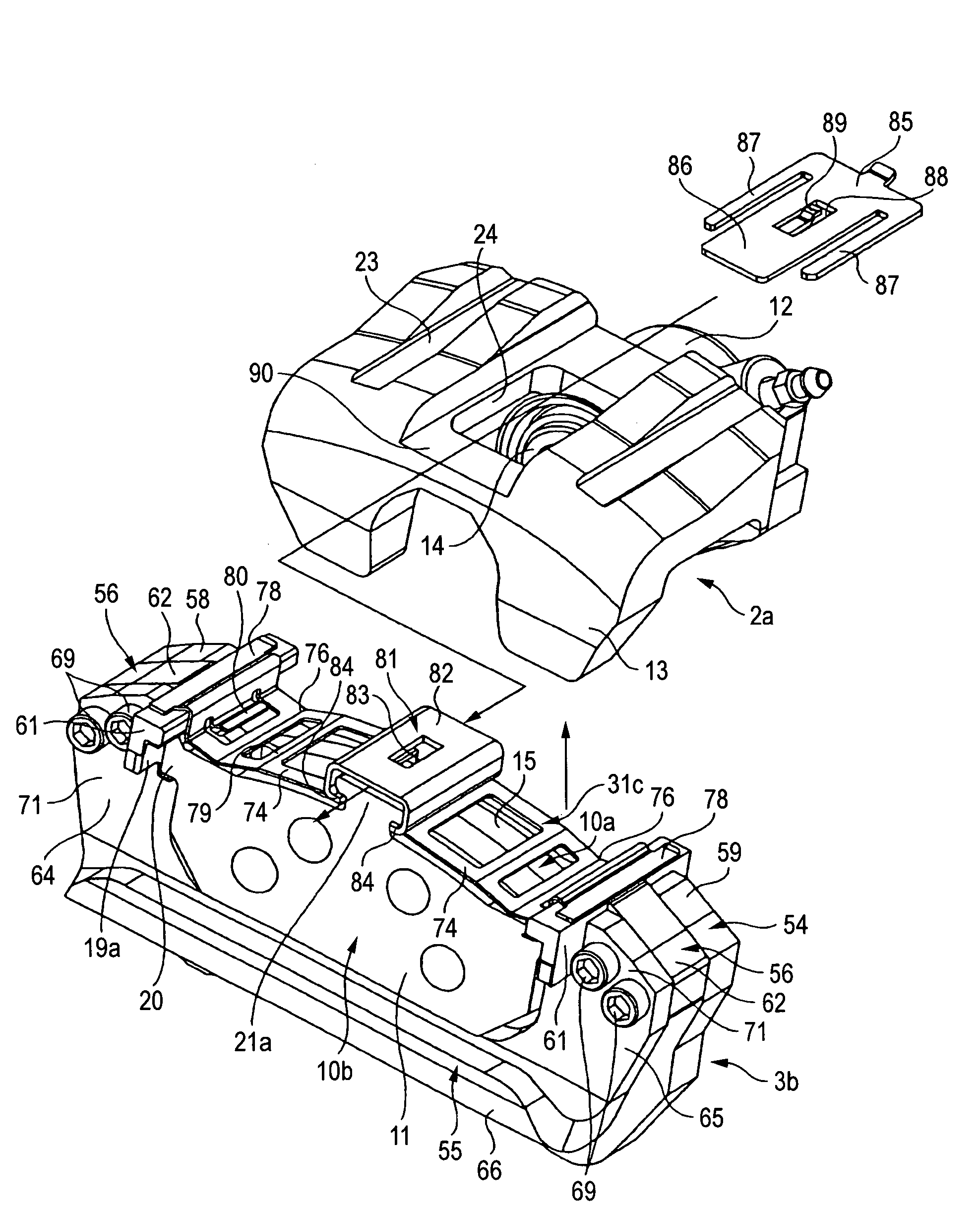
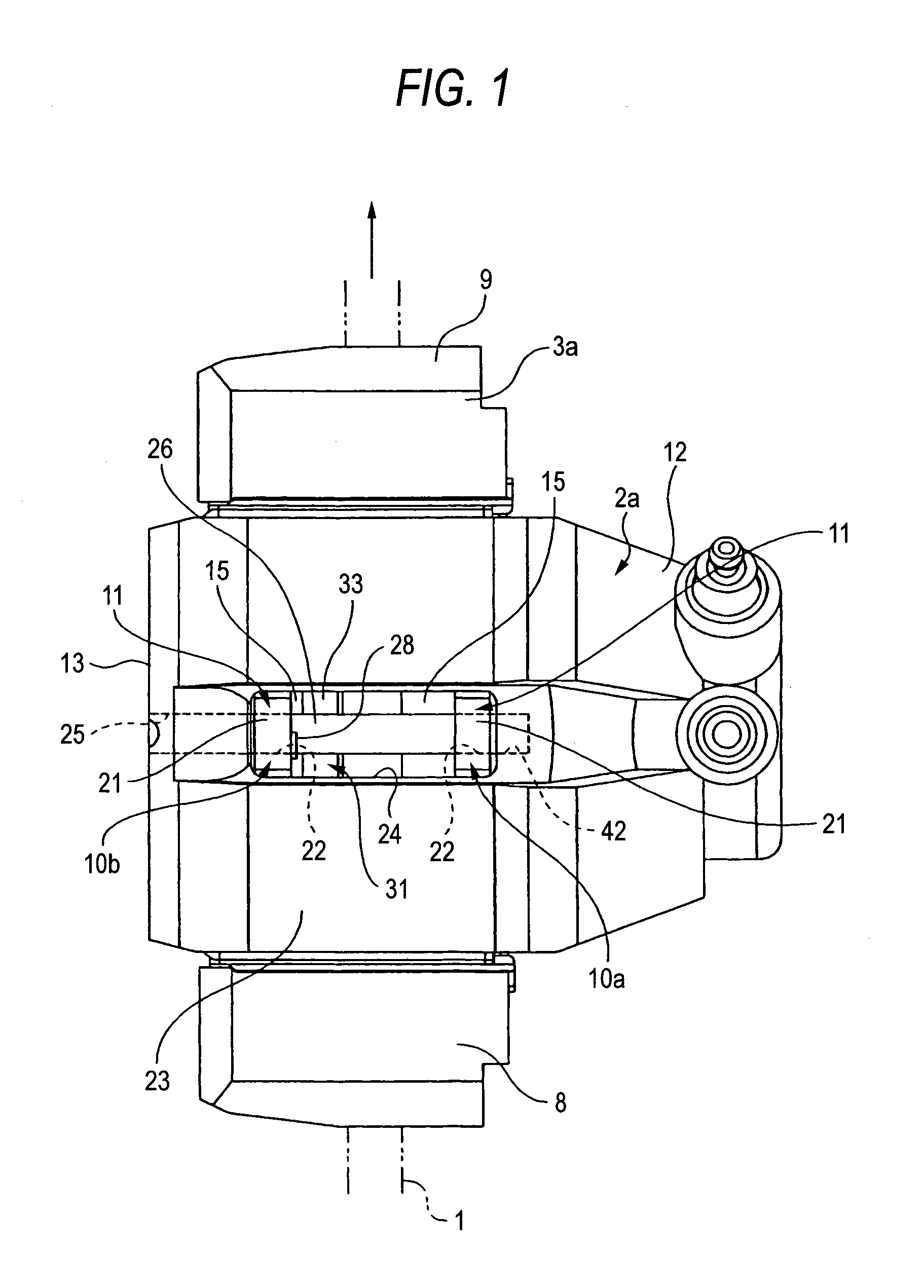
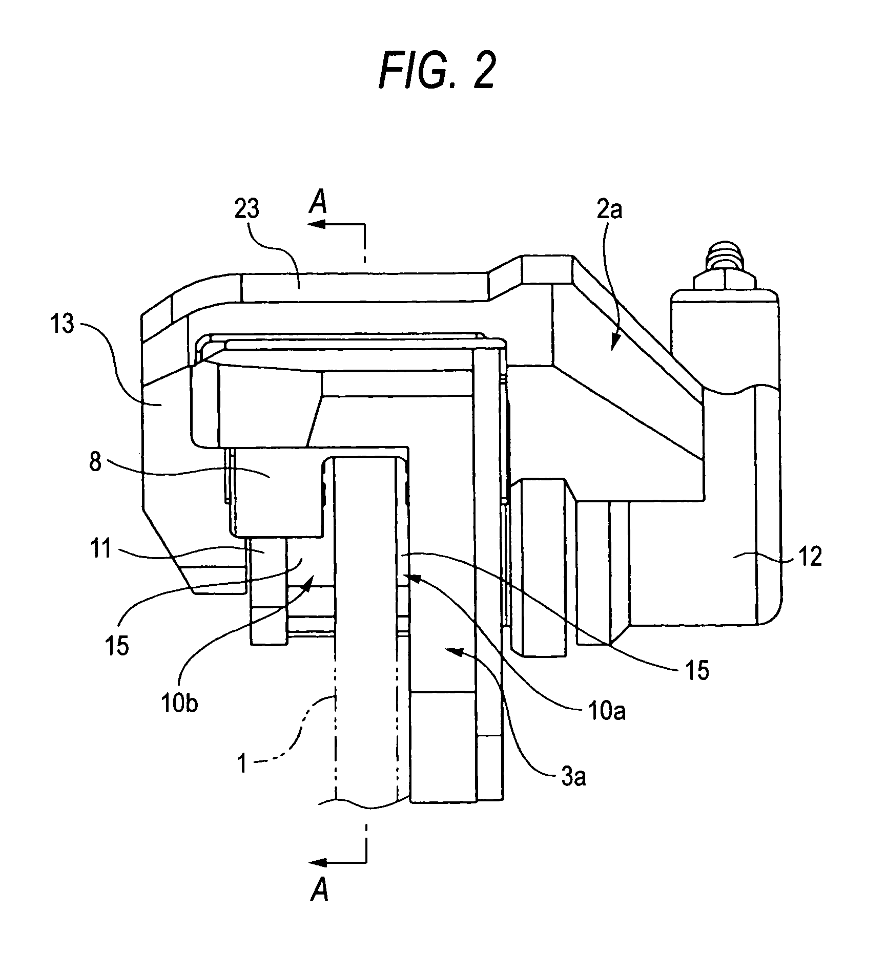
[0053]FIGS. 1 to 5 show a floating caliper disc brake according to a first embodiment of the present invention. A floating caliper disc brake of this embodiment includes a support member 3a, a pair of pads 10a, 10b and a caliper 2. Among them, the support member 3a is fixed to a vehicle body via a pair of mount holes 4, 4 provided at a lower end thereof at a position adjacent to a rotor 1 that rotates together with a corresponding wheel. The caliper 2a has a claw portion 13 provided at one end of a bridge portion 23 which straddles the rotor 1 and the pair of pads 10a, 10b and a cylinder portion 12 provided at the other end of the bridge portion 23 in which a piston 14 is mounted in a snugly-fitting fashion.

[0054]In addition, both the pads 10a, 10b are supported on the support member 3a in such a manner as to freely slide in an axial direction (a lateral direction in FIGS. 1, 2, and a direction towards / away from the viewer in FIGS. 3, 4) in such a state that the pads 10a, 10b are di...

second embodiment

[0066]FIGS. 6 to 10 show a floating caliper disc brake according to a second embodiment of the present invention. In the case of this embodiment, a caliper 2a is supported in such a manner as to freely be displaced in an axial direction of a rotor 1 (a lateral direction in FIGS. 6, 7 and a direction toward / away from the viewer in FIGS. 8, 9) relative to a support member 3a, and the caliper 2a is supported in such a manner as to freely be displaced in the axial direction of the rotor relative to respective pads 10a, 10b. Due to this, in the case of the embodiment, an elastic force is imparted to the caliper 2a in a direction in which the caliper 2a moves away from the rotor 1 by means of a hold spring 31a provided between the caliper 2a and the support member 3a. Namely, this hold spring 31a has a configuration illustrated in detail in FIGS. 9, 10, and longitudinally intermediate portions of a pair of pressing pieces 32a, 32a provided at both ends of the hold spring 31a are each bent...

third embodiment

[0071]FIGS. 11 to 15 show a floating caliper disc brake according to a third embodiment of the present invention. In the case of this embodiment, being different from the second embodiment that is illustrated in FIGS. 6 to 10, no entering portion 34 (refer to FIGS. 8 to 10) is provided at both end portions of a hold spring 31b which is adapted to enter between end faces of a caliper 2a in the width direction thereof and internal surfaces of respective rotation input side and rotation output side engagement portions 8, 9. Namely, in the case of the embodiment, as is illustrated in detail in FIGS. 14, 15, in a pair of pressing pieces 32b, 32b which make up the hold spring 31b, inward portions 36, 36 which are provided toward a longitudinal center of the hold spring 31b and outward portions 37, 37 which are provided toward longitudinal ends of the hold spring 31b are connected to stepped portions 38, 38. The inward portions 36, 36 are positioned further inward with respect to the radia...


PUM


Abstract

A caliper 2a is disposed between rotation input side and rotation output side engagement portions 8, 9 of a support member 3a so as to restrict the movement of the caliper 2a in a circumferential direction of a rotor 1. A guide pin 26 which supports the caliper 2a is passed through guide holes 22 formed in pressure plates 11 which make up respective pads 10b in such a manner as to be capable of sliding in an axial direction of the rotor 1, whereby the caliper 2a is supported on the respective pads 10b attachably and detachably to the support member 3a while being allowed to move in the axial direction of the rotor 1 relative to the respective pads 10b.

Description

[0001]The present application claims foreign priority based on Japanese Patent Application No. P.2004-268165, filed on Sep. 15, 2004, the contents of which are incorporated herein by reference.BACKGROUND OF THE INVENTION[0002]1. Field of the Invention[0003]The present invention relates to a floating caliper disc brake used for applying brakes on a vehicle.[0004]2. Related Art[0005]As disc brake assemblies for applying brakes on vehicles, there are floating caliper disc brake assemblies. In the floating caliper disc brake, a caliper is supported relative to a support member in such a manner as to be freely displaced in an axial direction and a cylinder and a piston are provided on only one side of the caliper relative to a rotor.[0006]In the floating caliper type of disc brakes, there are proposed various constructions depending on holding and sliding methods of calipers. In a construction referred to as pin-slide type, a caliper is supported by a guide pin on a support member in suc...

Claims


Application Information

Patent Timeline
Patent Type & Authority Patents(United States)
IPC IPC(8): F16D55/00F16D55/226F16D55/2265F16D65/097
CPCF16D55/2262F16D55/22655F16D65/095F16D65/0977F16D2055/0008F16D2055/007F16D55/226F16D65/092
Inventor MAEHARA, TOSHIFUMI
Owner AKEBONO BRAKE IND CO LTD
Why Eureka
Try Eureka