Method of winding up transfer film and device for performing transfer printing on printed sheets of paper

a technology of transfer film and printing sheet, which is applied in the direction of transportation and packaging, lithography, manufacturing tools, etc., can solve the problems of transfer film damage, and achieve the effect of improving operability

Inactive Publication Date: 2012-06-26
RYOBI
View PDF28 Cites 2 Cited by
  • Summary
  • Abstract
  • Description
  • Claims
  • Application Information

AI Technical Summary

Benefits of technology

[0007]In order to overcome the foregoing problems, it is an object of the present invention to provide a method of winding up a transfer film and a device for performing transfer printing on printed sheets of paper, capable of eliminating need to frequently replace the transfer film thereby to allow the transfer film to be used over a long period of time in a favorable manner.
[0010]The transfer film that has been fed from the feed roll is wound up on the windup roll, so that the transfer film can be lengthened by increasing the number of winds of the transfer film on the feed roll, with a compactly configured device as compared with one in which the transfer film is endlessly wound. Moreover, the transfer film that has been wound up on the windup roll is rewound to the teed roll, whereby the transfer operation can be carried out with the transfer film fed again from the feed roll toward the windup roll. Also, it is possible to eliminate a troublesome work that the windup roll and the feed roll are switched in position when the transfer film that has been fed from the feed roll is all wound up on the windup roll, and the transfer film is wound on a guiding roll or the like disposed between the two rolls to be wound up from the windup roll to the feed roll. A lateral position of the transfer film that is running along the feed path is detected during the rewind of the transfer film toward to the feed roll, and in a case where the detected position has changed, the feed roll is moved to the side that the lateral position of the transfer film has shifted to, thereby allowing the take-up position on the feed roll with respect to the transfer film to be adjusted to approximately the same position in a constant manner.
[0015]The transfer film that has been fed from the feed roll is wound up on the windup roll, so that the transfer film can be lengthened with a compactly configured device as compared with one in which the transfer film is endlessly wound. Moreover, the transfer film that has been wound up on the windup roll is rewound onto the feed roll, and during the rewind, the transfer film can be wound up with the feed roll caused to follow the positional change in lateral movement of the transfer film, so that the take-up position on the feed roll with respect to the transfer film can be adjusted to approximately the same position at all times. Accordingly, there can be provided a method of winding up a transfer film and a device for performing transfer printing on printed sheets of paper, capable of eliminating the need to frequently replace the transfer film and the need to switch the two rolls at the same time, thereby allowing the transfer film to be used favorably over a prolonged period of time.
[0016]The second position detecting part is provided on the feed path to detect a lateral position of the transfer film while the feed roll is feeding the transfer film, and the second controlling part is provided to control the driving mechanism so as to cause the feed roll to move to the side opposite the side that the lateral position of the transfer film has shifted to, based on the detected information from the second position detecting part; therefore, even when the fed transfer film is displaced in the lateral direction, the displaced position of the transfer film can be forcedly corrected while being fed toward the windup roll, and the take-up can be smoothly carried out. Also, the transfer printing can be performed at proper positions.
[0017]The second driving mechanism is provided to cause the windup roll to move in the lateral direction of the transfer film, the position detecting part identical to the aforementioned one is also provided on the windup path, and the third controlling part is provided to control the second driving mechanism so as to cause the windup roll to move to the side that the lateral position of the transfer film has shifted to, based on the detected information from the position detecting part. Thus, the transfer film can be wound up favorably onto the windup roll with changes in lateral position of the transfer film absorbed in the windup roll that takes up the transfer film fed from the feed roll, through the movement of the windup roll following the lateral positional change of the transfer film.
[0018]The change-over part is provided to provide a switch between the interlock state in which the rotary roller and the feed roll are integrally moved in the lateral direction of the transfer film, and a non-interlock state in which the rotary roller is released from the interlock to be rendered immovable in the lateral direction of the transfer film. The change-over controlling part is provided to provide an electrical switch among the three controlling parts so that, when the change-over part is switched to the interlock state, the second controlling part and the third controlling part are activated, and when the change-over part is switched to the non-interlock state, the controlling part is activated. Hence, only with the turning of the change-over part, not only the interlock between the rotary roller and the feed roll can be switched over, but also the drive of the three controlling parts can be switched over, which contributes to improved operability.

Problems solved by technology

Thus, the transfer film is necessarily repeatedly used, and there is a disadvantage in that the transfer film may be damaged at an early stage, which necessitates transfer film to be changed frequently.

Method used


Image

  • Method of winding up transfer film and device for performing transfer printing on printed sheets of paper
  • Method of winding up transfer film and device for performing transfer printing on printed sheets of paper
  • Method of winding up transfer film and device for performing transfer printing on printed sheets of paper

Examples


Embodiment Construction

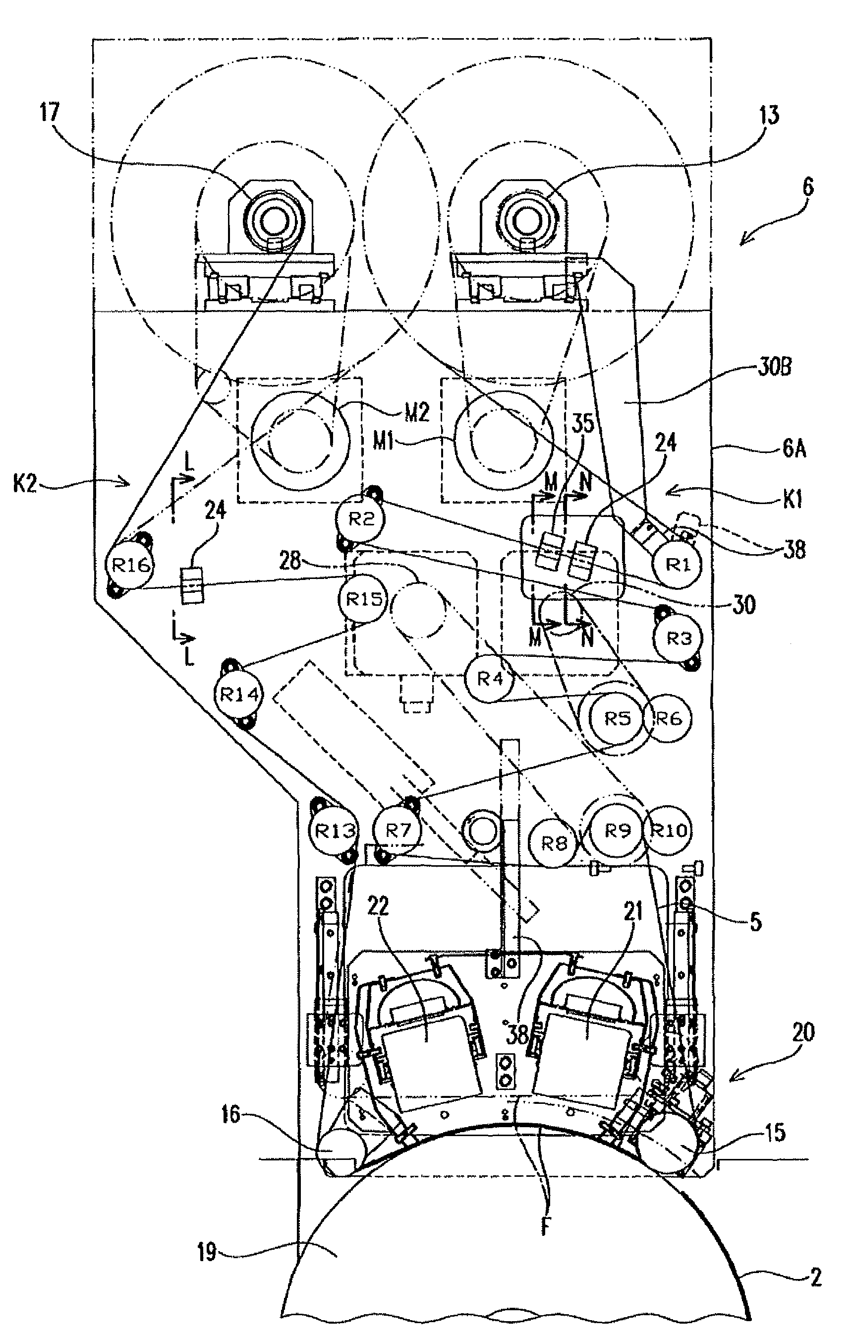
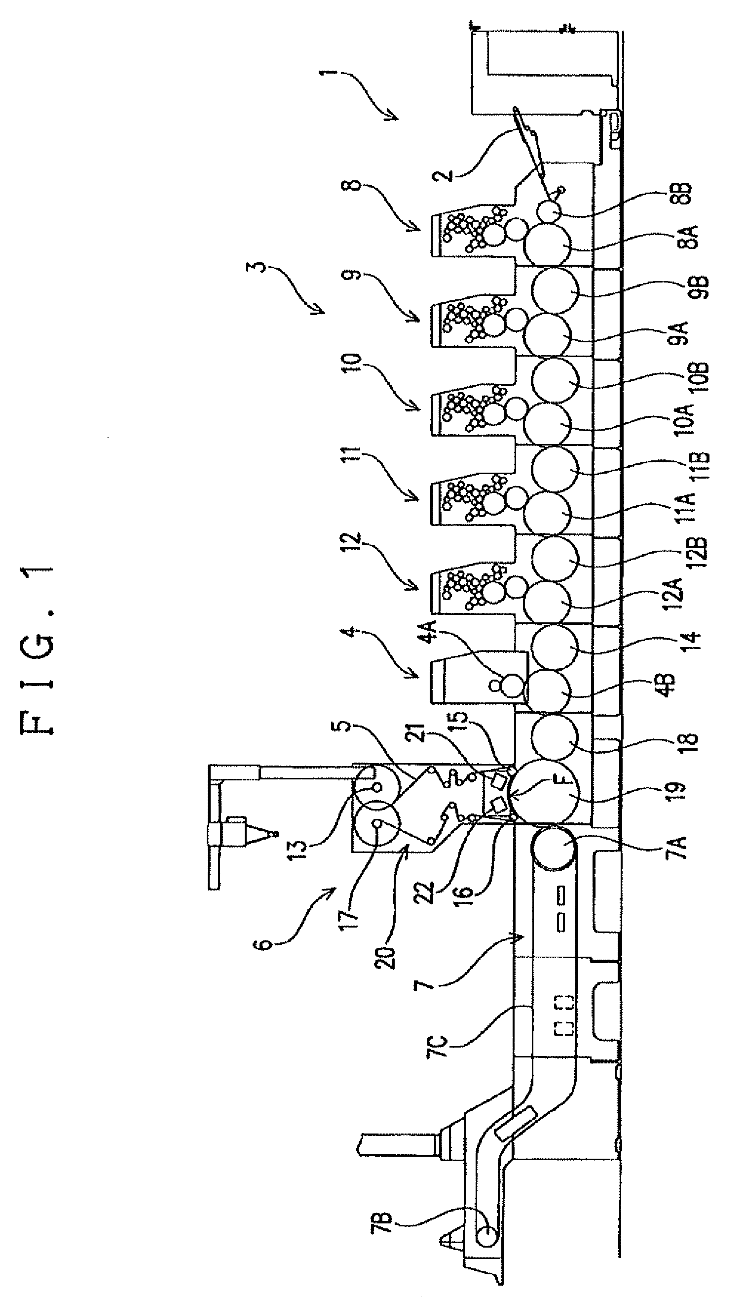
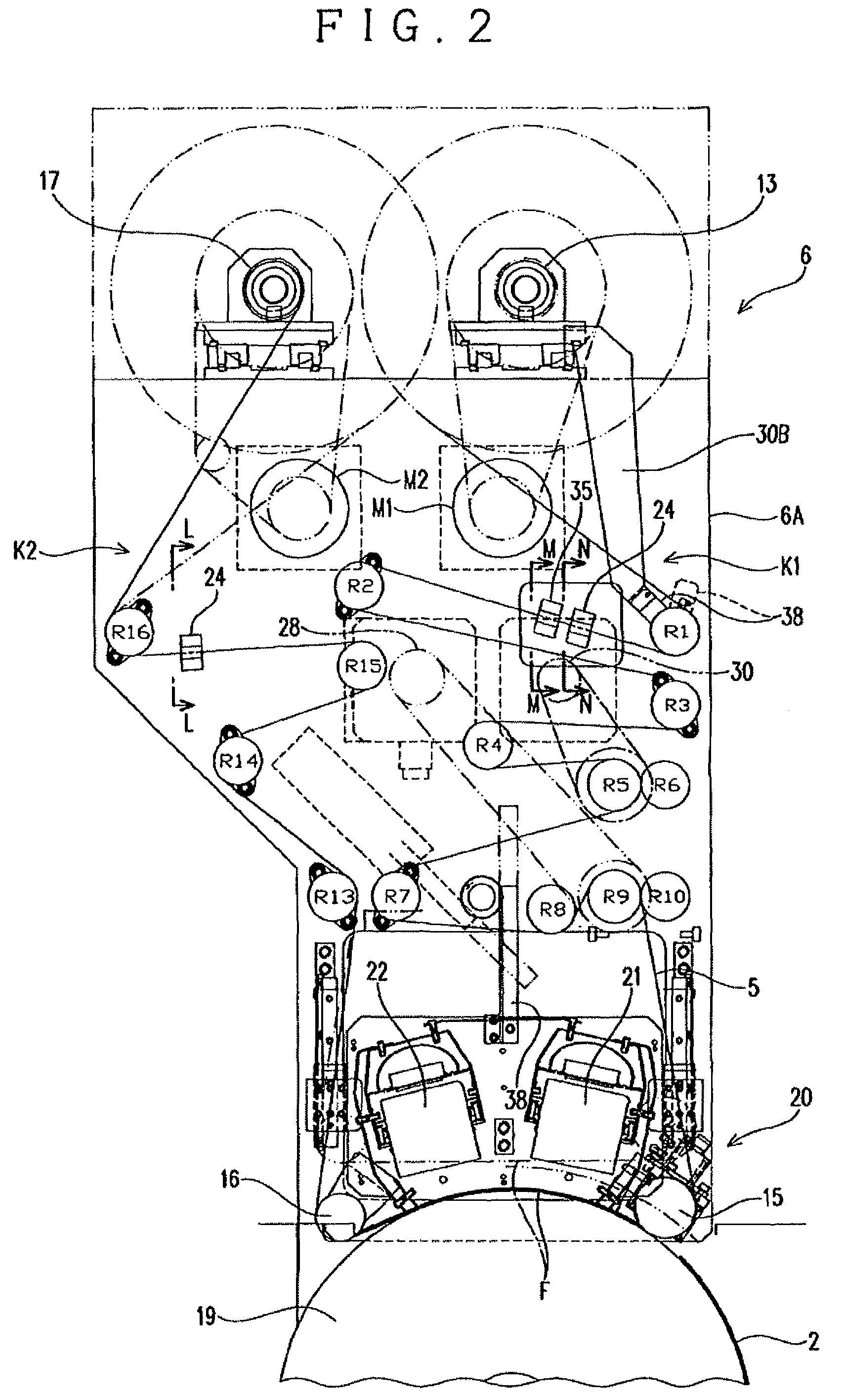
[0025]FIG. 1 shows an example of a printing press incorporating a transfer device 6 capable of treating the printed surfaces of printed sheets of paper by varnishing and gloss-finishing the printed surfaces with a resin varnish and transferring thereon gold foil, embossed patterns, hologram patterns, and the like. This printing press includes a sheet feeder section 1, a printer section 3, a varnish applicator section 4, a transfer section F, and a sheet discharge section 7. The sheet feeder section 1 feeds sheets of paper 2 one sheet at a time by means of a feeder device, a sheet separator device, and the like from a sheet stack table. The printer section 3 performs five-color printing on the sheets 2 fed from the sheet feeder section 1. The varnish applicator section 4 applies (coats) an ultraviolet curable resin varnish (also simply referred to as “a varnish”) onto the sheets 2 that have been printed in the printer section 3. The transfer section F presses a transfer film 5 made o...


PUM


Abstract

There is provided a method of winding up a transfer film and a device for performing transfer printing on printed sheets of paper, capable of eliminating the need to frequently replace the transfer film, thereby allowing the transfer film to be used over a prolonged time. According to the method of winding up a transfer film, the transfer film fed from a feed roll through a feed path is pressed onto a fed printed sheet to transfer patterns of the transfer film, and then the transfer film is wound up onto a windup roll through a windup path. During the rewind of the transfer film from the windup roll to the feed roll, a lateral position of the transfer film running along the feed path is detected, and the feed roll is moved in its axial direction to follow a lateral positional change of the transfer film.

Description

CROSS REFERENCE TO RELATED APPLICATION[0001]This application claims priority from Japanese Patent Application No. 2007-243809, which is incorporated herein by reference.BACKGROUND OF THE INVENTION[0002]1. Field of the Invention[0003]The present invention relates to a technique of pressing a transfer film onto printed sheets of paper to transfer thereon gold foil, embossed patterns, hologram patterns, and the like, thereby to increase added value of the printed surfaces, and more particularly, to a method of winding up a transfer film that is capable of winding up the transfer film in a favorable manner as well as a device for performing transfer printing on printed sheets of paper.[0004]2. Related Art[0005]There is proposed a gloss finishing apparatus for providing added value to printed sheets of paper in the above-mentioned manner. The apparatus includes a varnishing unit that applies an ultraviolet curable resin varnish (also simply referred to as “a varnish”) onto the printed sh...

Claims


Application Information

Patent Timeline
Patent Type & Authority Patents(United States)
IPC IPC(8): B31F1/07B41F7/02
CPCB41F19/062
Inventor YAMASHITA, TOSHIOHIROKAWA, KATSUSHINAKAMURA, TAKAHIKO
Owner RYOBI
Why Eureka
Try Eureka