
Spark gap arrestor

a technology of spark gap and arrestor, which is applied in the direction of spark gap details, overvoltage protection resistors, emergency protective arrangements for limiting excess voltage/current, etc., can solve the problems of preventing system down, communication devices, and affecting the safety of electrical appliances, etc., to reduce residual magnetism, improve the permeability of magnetic materials, and increase the attraction force to the arc discharge path

Inactive Publication Date: 2007-08-09
CSD CO LTD
View PDF8 Cites 2 Cited by
  • Summary
  • Abstract
  • Description
  • Claims
  • Application Information

AI Technical Summary

Benefits of technology

[0030] According to the structure of this invention, excellent advantages as follows can be provided.
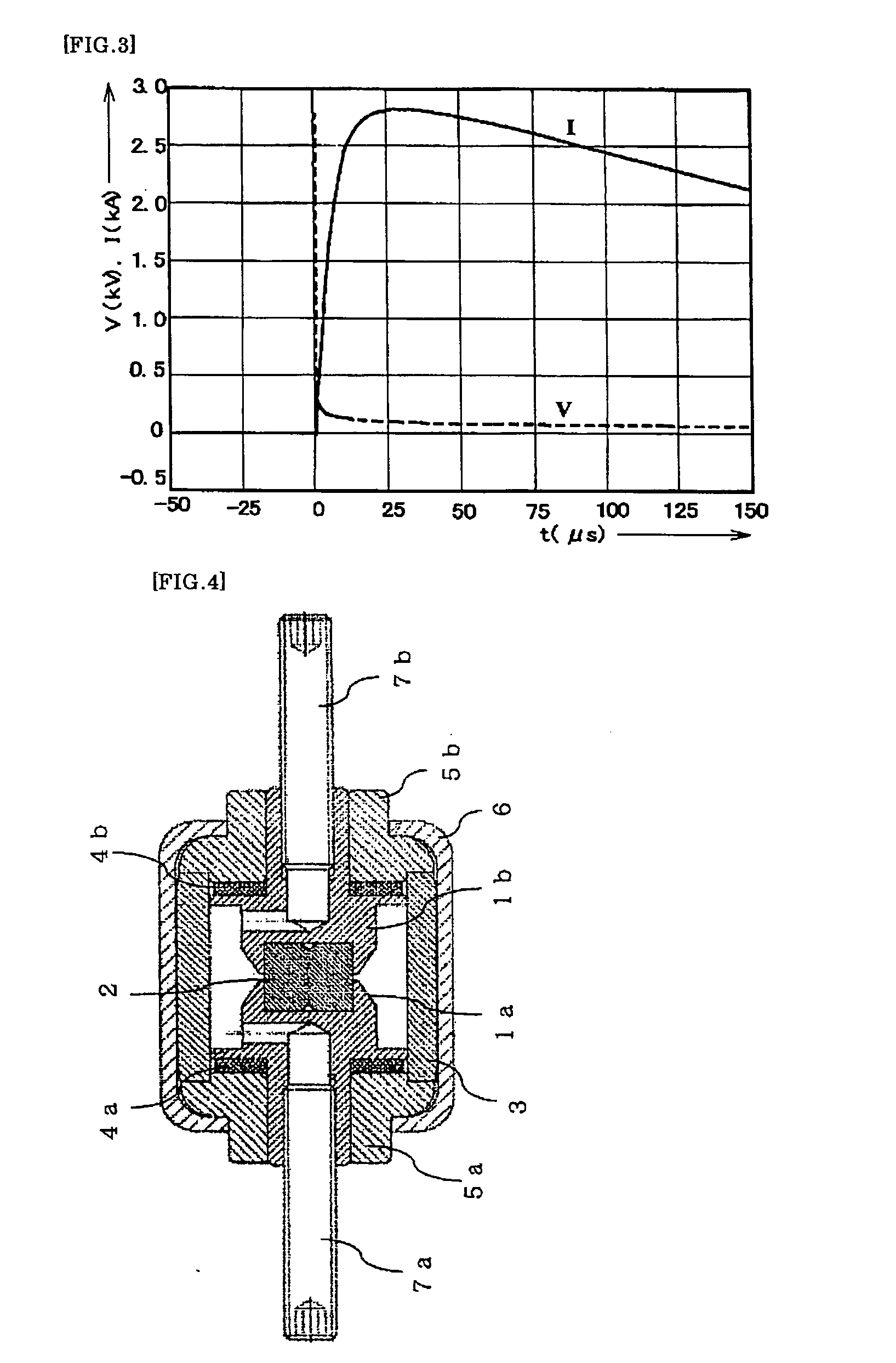
[0031] In a spark gap arrester arranged within a cylindrical metal case, as plural magnetic material metal rings concentric with a circular cross section of a conical or columnar electrode are arranged as arc-suppressing plates, anode and cathode voltage drops of an arc generated by a lightning impulse current and / or a power circuit follow current are increased and the follow current self-intercepting performance independent of the power-supply impedance is provided.
[0032] According to one embodiment of this invention in which proximal parts of two discharge electrodes are made of an ordinary conductive material such as copper or brass and only their distal end parts are made of a heat-resistant and arc-resistant material such as copper-tungsten or silver-tungsten, the function of the arrester can be guaranteed while the material cost is restrained.
[0033] According to a developed form of the foregoing embodiment in which a recessed part is provided in the proximal part of the electrode and a protruding part of the distal end part of the electrode is pressed into the recessed part, troublesome works such as soldering materials of different types can be avoided. Since a compression force is constantly applied to the electrode by the metal case, separation of the proximal part and the distal end part does not occur.
[0034] According to another embodiment of this invention in which the whole body except the distal end part and the proximal part of the conical or columnar electrode is covered with an organic arc-suppressing insulating material, extension of the arc discharge path is promoted and the follow current self-intercepting performance is enhanced.
[0035] According to still another embodiment in which a recessed part is provided on each of end surfaces facing each other of two discharge electrodes, with an insulator inserted across the two recessed parts, and the dimension of a spark gap is defined by the difference between the sum of the depths of the two recessed parts and the thickness of the insulator, the gap dimension can be prescribed with high accuracy while the assembling work is simplified.

Problems solved by technology

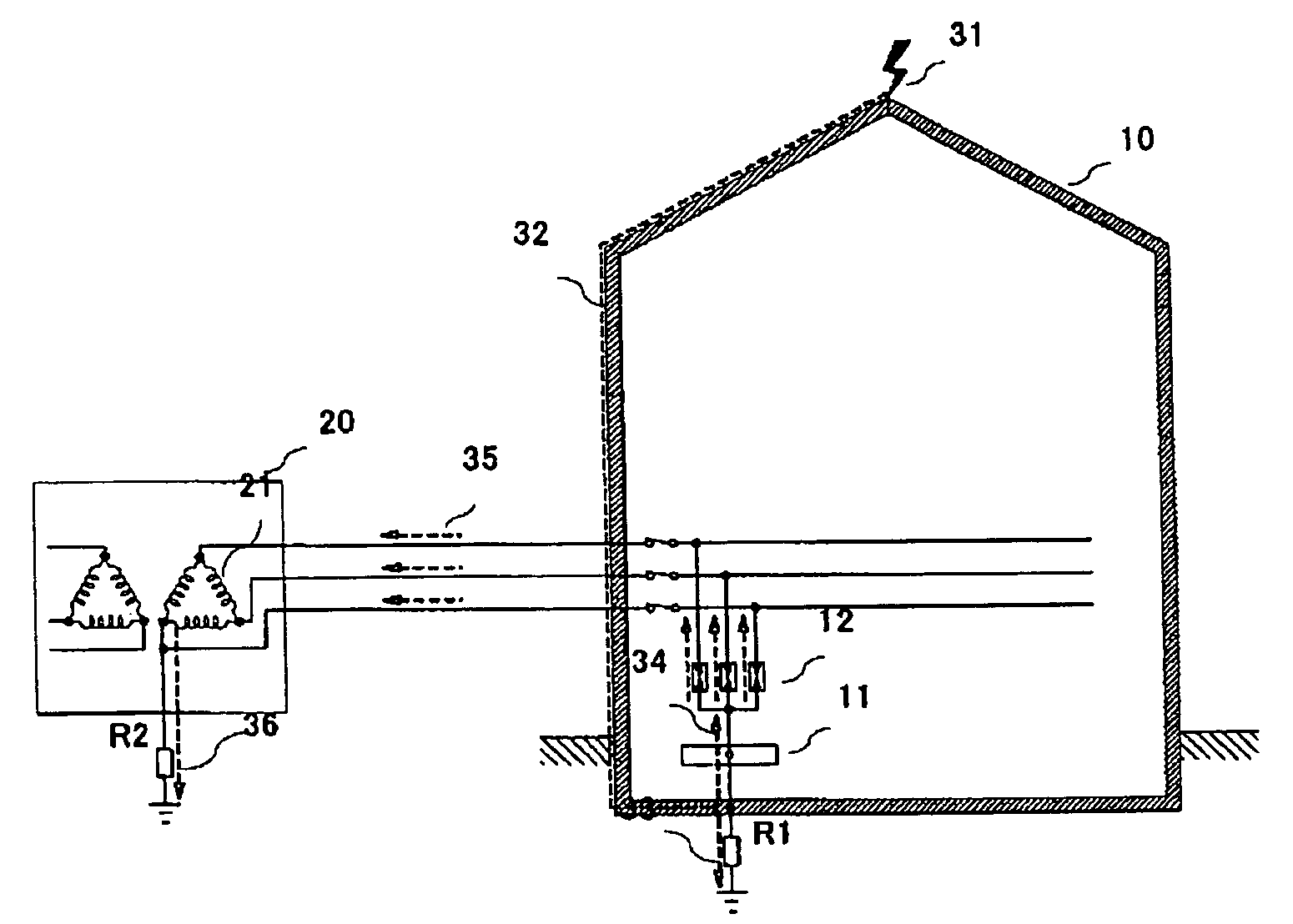
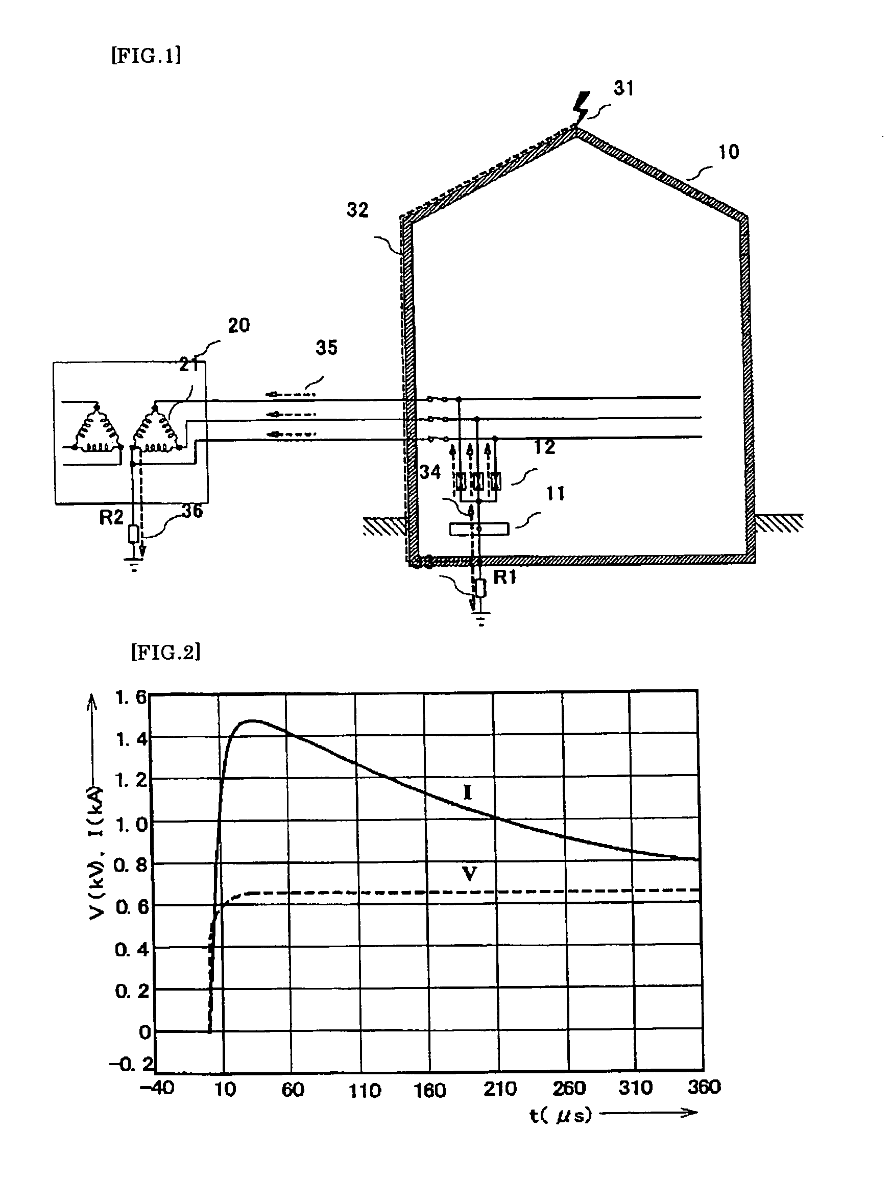
As distribution lines and telephone lines began to spread in the early 1900s, many accidents occurred in which insulating parts of electric and communication devices are broken by a lightning current that flowed into a building via these electric wires or a lightning current that flowed into the grounding on the outside of the building via these electric wires when lightning struck the building.
Particularly recently, since the degree of spreading of electronic devices is increased and they serve as the central parts of economy, transportation, electric power, communications and production management, preventive measures against system down due to lightning strike is an important technical problem.
The change of the reference waveform clarifies on one hand that the conventional arrester burns and explodes relatively easily at the time of lightning strike and does not serve as intended as the arrester, and suggests on the other hand that large increase in the amount of impulse current resistance of the lightning current arrester is necessary.
However, as shown in FIG. 2, since the varistor terminal voltage is maintained at several hundred V during the energization with the impulse current, the quantity of energy conversion within the varistor is large, and the varistor easily breaks and explodes particularly in the case of an impulse current having a long duration of wave tail.
Therefore, it cannot be used as a lightning current arrester.
However, in order to realize practical use of the spark gap as a lightning current arrester, there are two technical problems to be solved.
If this follow current is intercepted by an external protection circuit, inconvenience occurs such as the loss of the protective function against overvoltage due to shutdown of power supply to the load circuit or shutdown of the spark gap arrester from the power line.
2) When a large lightning impulse current flows, the air on the periphery of the aerial arc discharge path is heated and ionized and thus explosively expands and erupts, thereby affecting the peripheral wiring and equipment.
However, if the arc voltage is the above-described (UA+UK)=60 V, the follow current cannot be prevented.

Method used


Image

  • Spark gap arrestor
  • Spark gap arrestor
  • Spark gap arrestor

Examples


Embodiment Construction

[0049] Hereinafter, the structure and function of an arrester for a low-voltage AC power circuit according to this invention will be described in detail with reference to FIGS. 7 and 8.

[0050]FIG. 7 is a longitudinal sectional view of a cylindrical sealed arrester. Its components are produced and arranged in a rotationally symmetrical manner about a center axis. Two discharge electrodes have their proximal parts made of copper members 102a, 102b, which are ordinary conductors, and have their distal end parts made of copper-tungsten chips 101a, 101b having excellent heat resistance and arc resistance. The proximal parts 102a, 102b and the distal end parts 101a, 101b are integrated without performing any troublesome processing such as soldering, since protruding parts of the distal ends parts are fitted into recessed parts provided in the proximal parts. The combination of the recessed and protruding parts of the proximal parts and the distal end parts may be the opposite. The dischar...


PUM


Abstract

[Problem] To realize a spark gap arrester of a sealed structure in which a follow current is eliminated by increasing voltage drop independent of an arc current and thereby preventing restrike due to a power-supply voltage after passage of a lightning current. [Means for Resolution] In a cylindrical metal case housing a spark gap, plural magnetic material metal rings concentric with a conical or columnar electrode constituting the spark gap are arranged as arc-suppressing plates. An arc generated by passage of a lightning current is led to the arc-suppressing plate on the outer periphery, and restrike due to a power-supply voltage after passage of a lightning current is prevented by an arc voltage generated on both sides of the arc-suppressing plate.

Description

TECHNICAL FIELD [0001] This invention relates to an arrester structure that is installed in a low-voltage AC power circuit and adapted for bypassing and discharging a lightning current to the ground in order to protect an electronic device sensitive to overvoltage when lightning strike occurs. BACKGROUND ART [0002] After the Franklin lightning conductor was invented in the late 1700s, lightning conductors and conductor wires were exclusively used as devices for protecting buildings from lightning for about 200 years (external protection from lightning). This is because damage could be minimized by receiving a lightning stroke current by these conductors and discharging it to the ground at the shortest distance via a grounding electrode. As distribution lines and telephone lines began to spread in the early 1900s, many accidents occurred in which insulating parts of electric and communication devices are broken by a lightning current that flowed into a building via these electric wir...

Claims


Application Information

Patent Timeline
IPC IPC(8): H02H9/06H01T1/04H01T4/12
CPCH01T4/12H01T1/04H02H9/06H01T4/00
Inventor KATO, KOJIRO
Owner CSD CO LTD
Learn More