
Magnetic track breaker with composite working of permanent magnet and electromagnet

A magnetic rail brake and electromagnetic composite technology, which is applied in the direction of brakes interacting between brake components and rails, railway braking systems, railway car body parts, etc., can solve the problems of insensitive braking response, incomplete disconnection of braking force, The problem of excessive reverse torque of the rotating shaft can reduce the phenomenon of residual magnetism, enhance the braking effect and reduce the effect of reverse torque

Active Publication Date: 2015-02-04
江阴智产汇知识产权运营有限公司
View PDF4 Cites 0 Cited by
  • Summary
  • Abstract
  • Description
  • Claims
  • Application Information

AI Technical Summary

Problems solved by technology

[0005] The purpose of the present invention is to provide a new type of brake system for overcoming the insensitivity of the braking response due to the insensitivity of the braking response due to the excessive reverse torque of the rotating shaft when the permanent magnet rail brake is not working in the prior art. Magnetic track brake with permanent magnet and electromagnetic composite work with good braking effect

Method used


Image

  • Magnetic track breaker with composite working of permanent magnet and electromagnet
  • Magnetic track breaker with composite working of permanent magnet and electromagnet
  • Magnetic track breaker with composite working of permanent magnet and electromagnet

Examples


Embodiment Construction

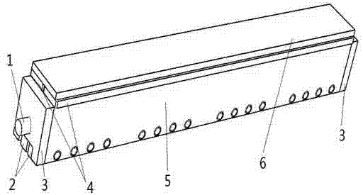
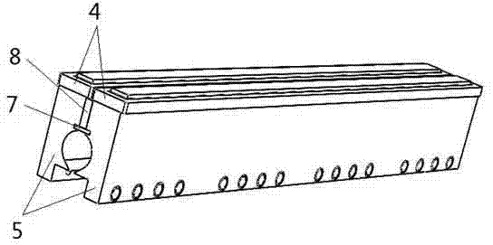
[0018] Such as image 3 As shown, the magnetic track brake has a rotating shaft 1, which is composed of two half shafts 10, a left shaft head 9, a right shaft head 12 and a permanent magnet 11 to form a circular shaft body. The two semi-shafts 10 are arranged opposite to each other, and an axially penetrating through groove is left in the middle of the two half-shafts 10. A permanent magnet 11 with the same size as the through groove is embedded in the through groove. The magnetization direction of the permanent magnet 11 is toward the two sides. The directions of the two semi-axes 10 are N pole and S pole respectively.

[0019] The left shaft head 9 is fixedly connected to the left ends of the two semi-shafts 10, the right shaft head 12 is fixedly connected to the right ends of the two half shafts 10, the left shaft head 9 has a long length, and is used to connect the driving mechanism for driving the rotating shaft 1, and the left Both the shaft head 9 and the right shaft h...


PUM


Abstract

The invention discloses a magnetic track breaker with the composite working of a permanent magnet and an electromagnet. A rotating shaft comprises two half shafts and a second permanent magnet, wherein the two half shafts made of permeability magnetic materials are arranged oppositely; a through groove which runs through in an axial direction is formed at the middle of the two half shafts; the second permanent magnet of which the size is accordant with the size of the through groove is embedded inside the through groove; a bracket structure comprises side plates which are made of permeability magnetic materials and are positioned at the front and rear sides and a middle isolating plate which is fixedly connected with the two side plates and is made of non-permeability magnetic materials; the rotating shaft is arranged below the middle isolating plate; a groove which runs through the axial direction is formed between the two side plates and the part above the middle isolating plate; a first permanent magnet of which the size is accordant with the size of the groove is put into the\ groove; coils are correspondingly sleeved at circles of the upper parts of the side plates at two sides; and pole shoes are connected with the lower parts of the side plates. The backward torque of the rotating shaft while rotating is effectively reduced by controlling the currents and the directions of the coils; and after the magnetic track breaker works stably, the current is cut off; when an extra brake force is needed, the mode of composite brake of the electromagnet and the permanent magnet is adopted, so that the brake effect is further enhanced.

Description

technical field [0001] The invention relates to a magnetic track brake of a railway train vehicle, which realizes the braking or release of the railway train vehicle. Background technique [0002] The combined control of multiple braking methods in rail vehicles will greatly guarantee the driving safety of high-speed rail vehicles. At present, disc brakes are widely used in railway passenger vehicles, which reduces the degree of thermal damage to the wheel tread compared with tread brakes. However, as a sticking brake, the braking force produced by the disc brake is still limited by sticking conditions. Although the anti-skid device can be used to make the braking force approach the adhesion limit, when the train speed needs to be further increased, the braking distance must be extended to meet the vehicle speed-up requirements. Braking needs of urban rail vehicles. [0003] Magnetic track brakes include electromagnetic track brakes and permanent magnet track brakes. Amon...

Claims


Application Information

Patent Timeline
Patent Type & Authority Patents(China)
IPC IPC(8): B61H7/08
Inventor 姚明王亮张新华何仁武晓晖陈士安
Owner 江阴智产汇知识产权运营有限公司
Learn More