Eddy current deceleration device

a technology of deceleration device and eddy current, which is applied in the direction of mechanical equipment, asynchronous induction clutch/brake, transportation and packaging, etc., can solve the problems of dragging braking, insufficient magnetization, and difficulty in increasing braking force, so as to prevent dragging torque, high magnetic flux density, and prevent magnetic leakage to the rotor

Inactive Publication Date: 2005-09-27
ISUZU MOTORS LTD
View PDF19 Cites 26 Cited by
  • Summary
  • Abstract
  • Description
  • Claims
  • Application Information

AI Technical Summary

Benefits of technology

[0014]Also, during braking, the respective permanent magnets of the first and second magnet rings are in a condition in which two permanent magnets are adjacent with the same polarity, so these permanent magnets constitute sets of pairs, which exhibit strong magnetic force. Also, the respective permanent magnets of the first and second magnet rings can be separately magnetized in the first magnet ring and the second magnet ring. When this is done, as already described, magnetization of the permanent magnets is achieved with these being of a length that is half the length of the sets of pairs, so the intervals between adjacent permanent magnets in the circumferential direction can be made small yet ample magnetization can still be achieved. Braking force is thereby improved.
[0016]According to the present invention, by rotating at least one of the magnet ring and magnetic ring so as to put these rings in a phase such that permanent magnets, of the permanent magnets of the magnet ring, that are of the same polarity as the permanent magnets sandwiching the magnetic members, face the magnetic members between the permanent magnets of the magnetic ring, the magnetism that is generated from the permanent magnets of the magnetic ring and the magnet ring can be respectively transmitted to the rotor, making it possible to perform strong deceleration braking of the rotary shaft with a high magnetic flux density.
[0017]Contrariwise, by putting these rings in a phase in which permanent magnets, of the permanent magnets of the magnet ring, that are of unsame polarity to the permanent magnets that sandwich the magnetic members face the magnetic members between the permanent magnets of the magnetic ring, the permanent magnets of the magnet ring and the magnetic ring can be mutually magnetically short-circuited, thereby making it possible to prevent magnetic leakage to the rotor and so prevent dragging torque from being generated.
[0021]According to the present invention, the permanent magnets of the magnetic ring can be made smaller and of weaker magnetic force than the permanent magnets of the magnet ring, so the thickness of the magnetic ring in the radial direction can be reduced.

Problems solved by technology

On the other hand, if the number of permanent magnets j that are to be provided is prioritized, magnetization becomes insufficient because the gap therebetween is reduced.
It was therefore difficult to increase the braking force.
Also, as shown in FIG. 35, although, when the deceleration braking is turned off, a dominant part of the magnetism of the permanent magnets j is shielded within the casing e by the pole pieces 1, some portion thereof leaks to the rotor c through the supports m made of non-magnetic material, thereby constituting a magnetic leakage circuit p. Weak eddy currents are thereby generated in the rotor c, giving rise to dragging braking, which has an adverse effect on fuel consumption of the vehicle.

Method used


Image

  • Eddy current deceleration device
  • Eddy current deceleration device
  • Eddy current deceleration device

Examples


Embodiment Construction

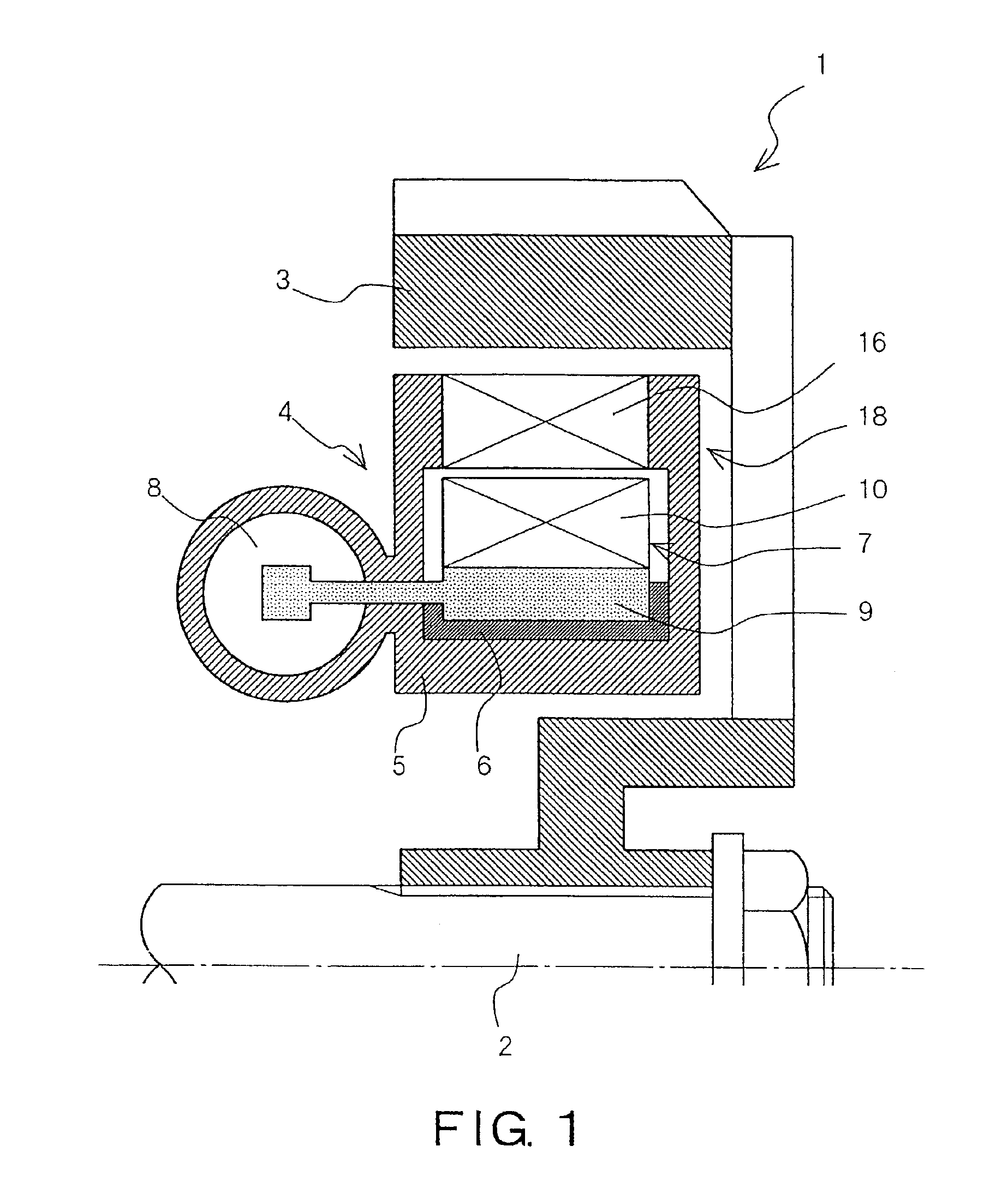
[0067]An embodiment of the present invention according to claim 1 is described with reference to the appended drawings.

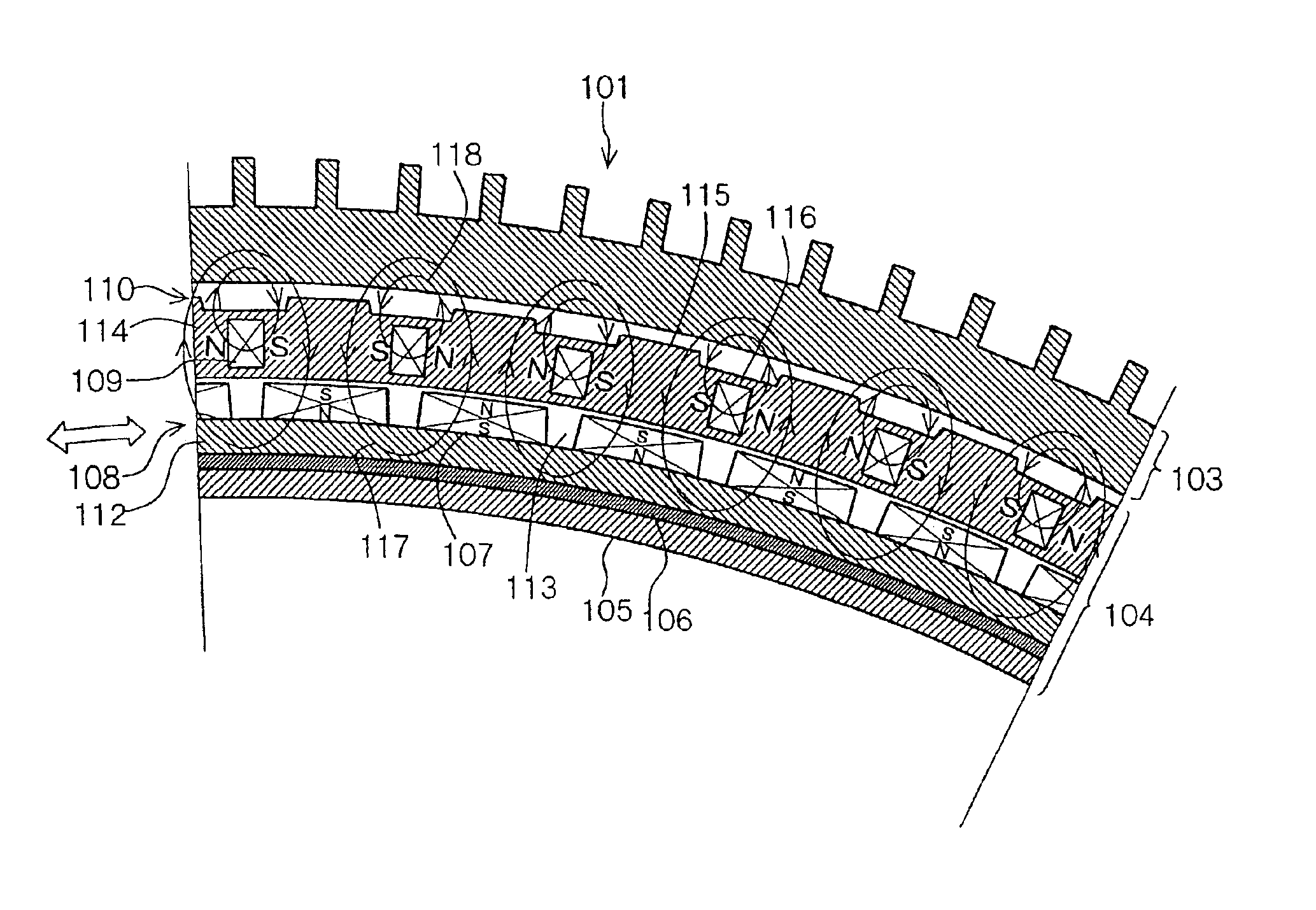
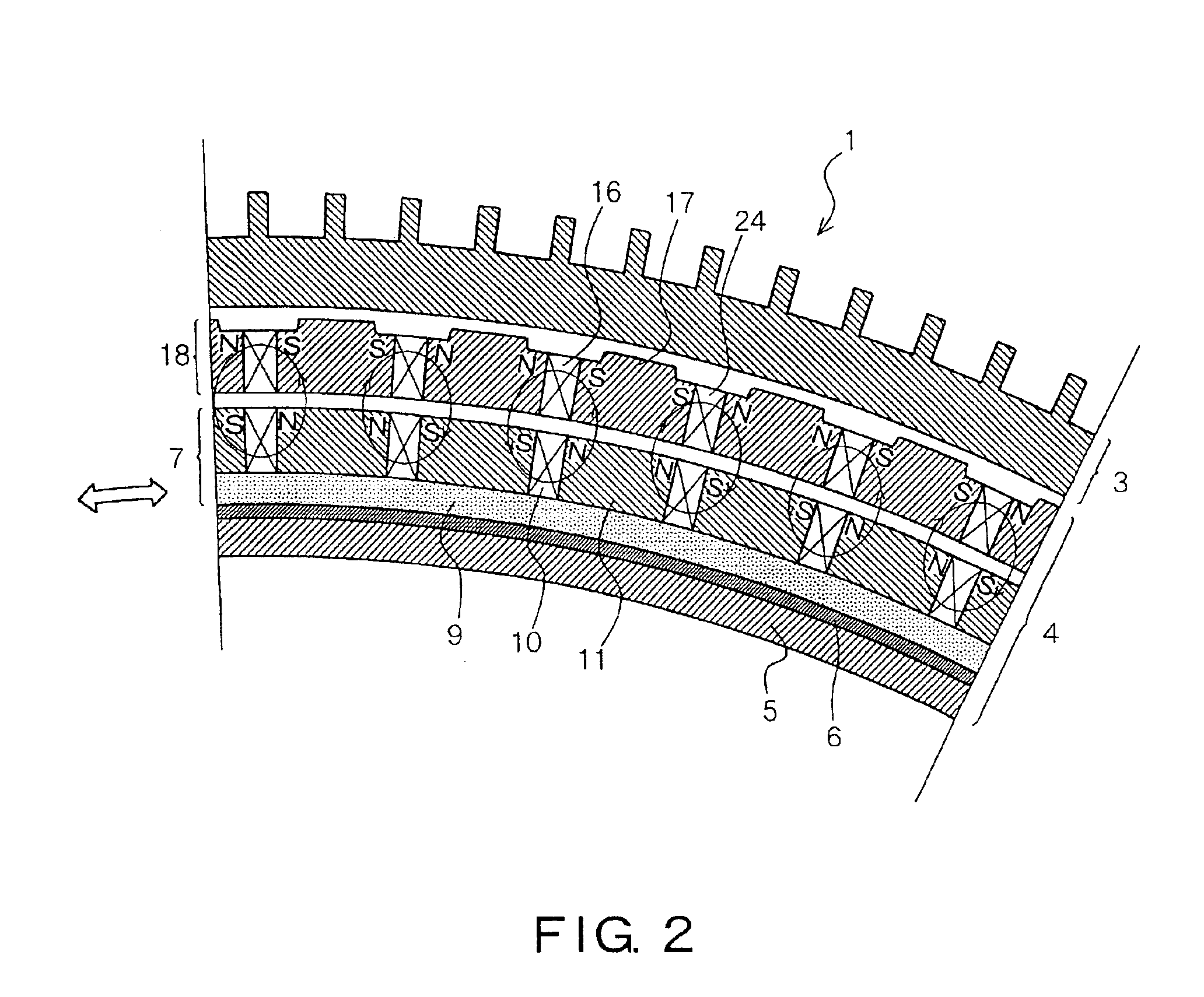
[0068]FIG. 1 shows a side cross-sectional view of an eddy current deceleration device according to an embodiment of the invention. FIG. 2 shows a front cross-sectional view of the brake-OFF condition of this device. FIG. 3 shows a front cross-sectional view of the brake-ON condition of this device.

[0069]As shown in FIG. 1, this eddy current deceleration device 1 comprises a drum-shaped rotor 3 that is mounted on a rotary shaft 2 of the power transmission system of a vehicle and a stator 4 (source of magnetic force) mounted on a fixed system such as the vehicle transmission. This eddy current deceleration device is capable of deceleration braking of the vehicle by generating eddy currents in the rotor 3 by supplying magnetism to the rotor 3 from the stator 4 and of releasing the deceleration braking by shielding the magnetism within the stator 4.

[0070]The stator 4 co...


PUM


Abstract

An eddy current deceleration device includes a rotor mounted on a rotary shaft; a first magnet ring arranged facing this rotor and including permanent magnets that are arranged at prescribed intervals in the circumferential direction and such that the poles thereof facing each other in the circumferential direction are of a same polarity, and magnetic members interposed between these permanent magnets; and a second magnet ring arranged between this first magnet ring and the rotor and including permanent magnets and magnetic members which are similar to those of the first magnet ring; at least one of the first and second magnet rings being freely rotatable. The permanent magnets of the first and second magnet rings can be magnetized separately between the first and second magnet rings.

Description

REFERENCE TO RELATED APPLICATION[0001]The present invention claims priority from Japanese Patent Application 2002-154349 filed in Japan on 28th May 2002 and Japanese Patent Application No. 2002-187293 filed in Japan on 27th Jun. 2002. The content of these Japanese applications is hereby incorporated in the specification of the present application by reference.BACKGROUND OF THE INVENTION[0002]1. Field of the Invention[0003]The present invention relates to an eddy current deceleration device that applies deceleration braking to a vehicle.[0004]2. Description of the Related Art[0005]The present inventor has previously developed an eddy current deceleration device as shown in FIG. 34 to FIG. 36. As shown in these Figures, this eddy current deceleration device a comprises a drum-shaped rotor c that is mounted on a power transmission system such as a drive shaft b of a vehicle and a stator d (source of magnetic force) mounted on a fixed system such as a vehicle transmission. The vehicle i...

Claims


Application Information

Patent Timeline
Patent Type & Authority Patents(United States)
IPC IPC(8): H02K49/04H02K49/00
CPCH02K49/043H02K49/046
Inventor KUWAHARA, TOHRU
Owner ISUZU MOTORS LTD
Why Eureka
Try Eureka