
Energy-saving servo motor
A technology of servo motors and components, applied in the direction of magnetic circuit static parts, magnetic circuit shape/style/structure, magnetic circuit rotating parts, etc., can solve the problem that the electronic motor controller cannot directly control the operating speed of the induction motor and the system efficiency is low , waste of electric energy and other issues, to achieve the effect of saving manufacturing resources, high magnetic energy product, and improving energy saving effect
- Summary
- Abstract
- Description
- Claims
- Application Information
AI Technical Summary
Problems solved by technology
Method used
Image

Examples
Embodiment Construction
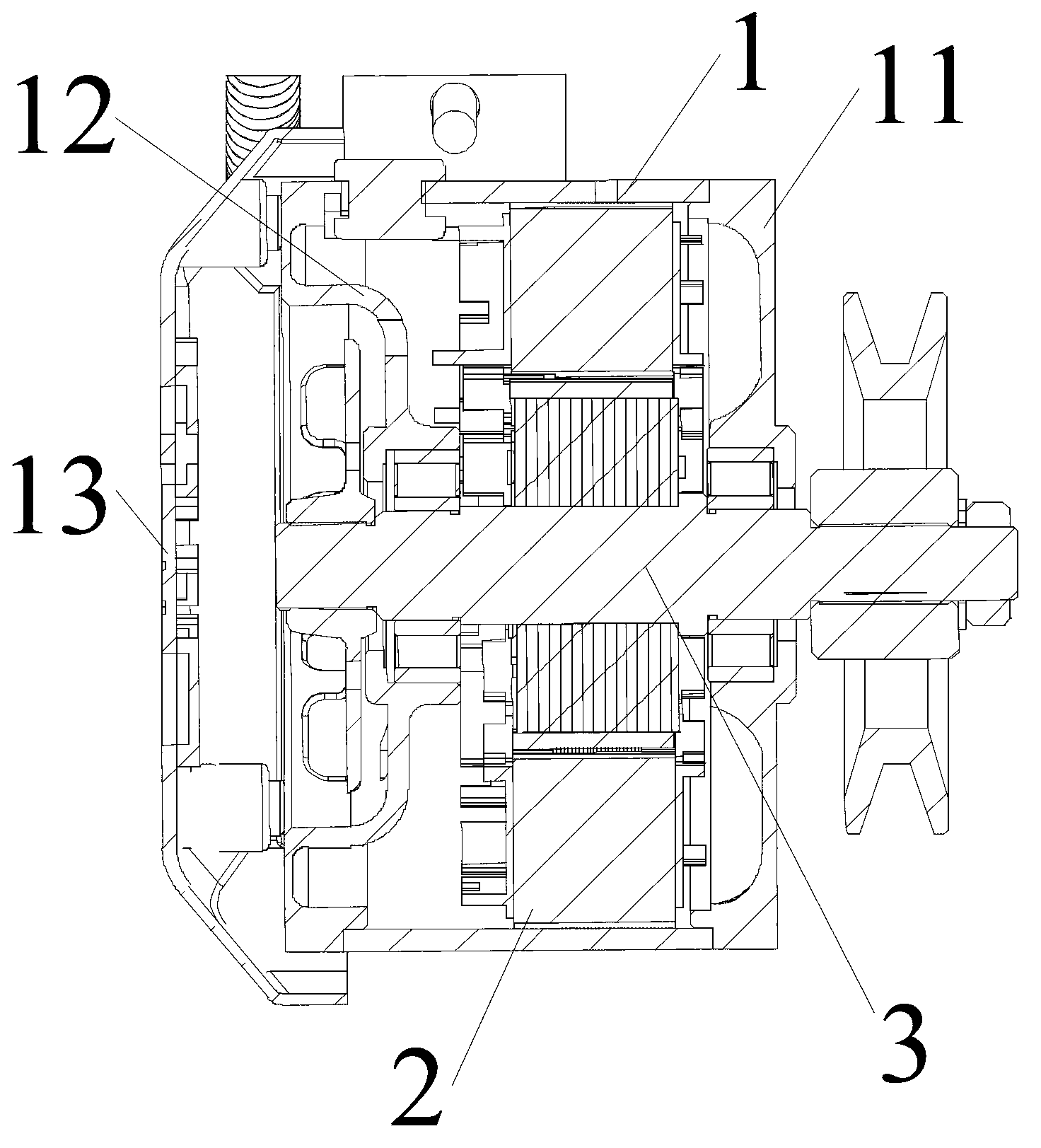
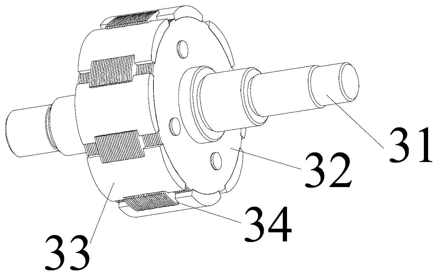
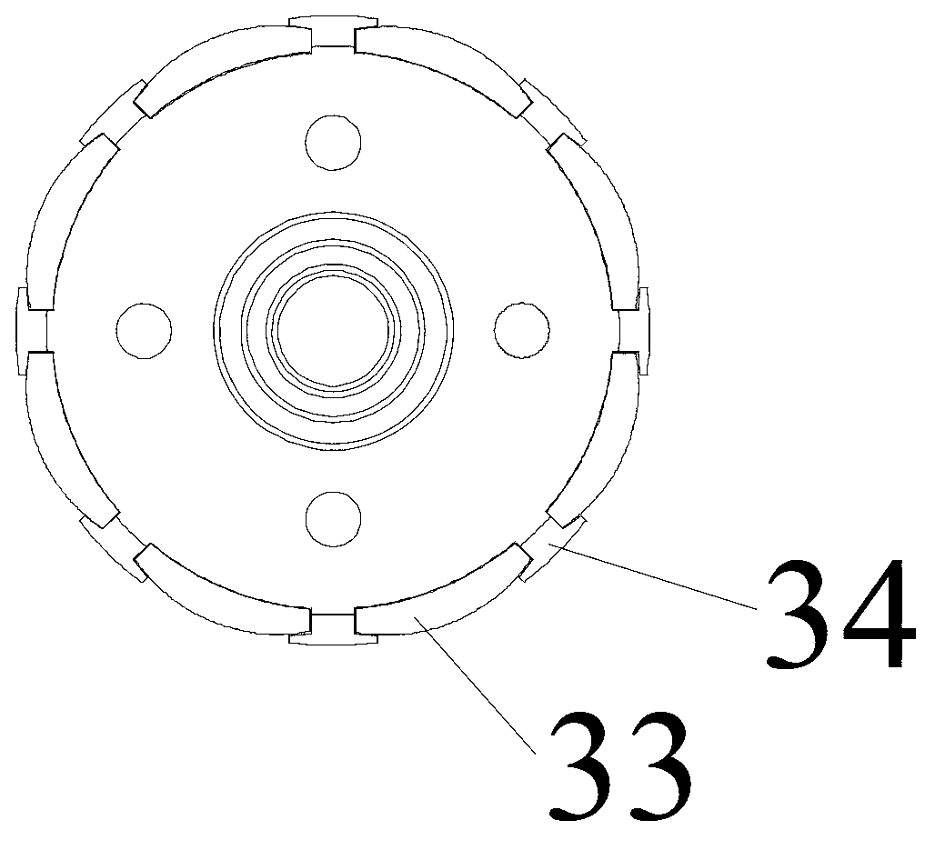
[0027] Such as figure 1 Shown is an energy-saving servo motor of the present invention, including a casing 1 , a stator assembly 2 and a rotor assembly 3 . Such as figure 2 with image 3 As shown, the rotor assembly 3 includes a motor shaft 31 and a rotor core 32 sleeved and fixed on the motor shaft 31. The rotor core 32 is formed by laminating several silicon steel sheets. The rotor assembly 3 has no field winding. A plurality of magnetic steels 33 made of NdFeB materials are installed on it, and the magnetic steels 33 are in the shape of tiles. The silicon steel sheet in the middle part of the rotor core 32 has 33 magnets distributed along the circumferential direction on the outer peripheral surface. There are identical T-shaped bumps 34, and the bumps 34 protrude outward along the radial direction of the silicon steel sheet. The bumps 34 on all the silicon steel sheets in the middle are stacked together to form a draw-in groove equal in number to the magnetic steel 33....
PUM
 Abstract
Description
Claims
Application Information