Electromagnetic switching apparatus

A technology of electromagnetic switches and equipment, applied in the direction of electromagnetic relays, electromagnetic relay details, circuits, etc., can solve problems affecting electronic components and electromagnetic switching equipment, coil noise, etc.

Inactive Publication Date: 2004-04-14
MATSUSHITA ELECTRIC WORKS LTD
View PDF2 Cites 42 Cited by
  • Summary
  • Abstract
  • Description
  • Claims
  • Application Information

AI Technical Summary

Problems solved by technology

However, in such controllers, the coil emits a large amount of noise, which adversely affects electronic components and electromagnetic switching devices, etc., near the coil.

Method used


Image

  • Electromagnetic switching apparatus
  • Electromagnetic switching apparatus
  • Electromagnetic switching apparatus

Examples


no. 1 example

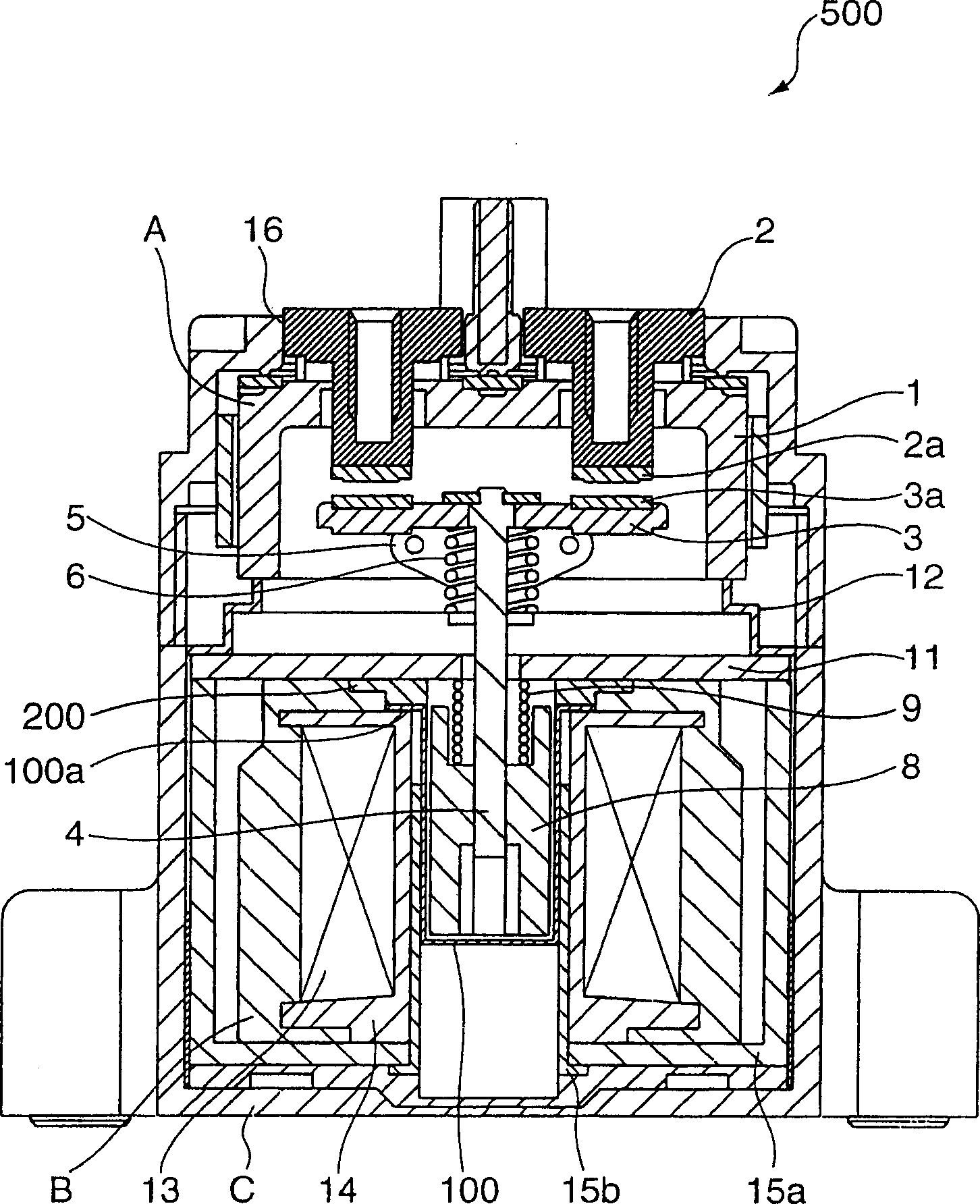
[0051] figure 1 It is a side sectional view of the electromagnetic switch device as the first embodiment of the present invention. Since the basic structure of the first electromagnetic switch device is the same as that of the conventional device, only the characteristic parts of the first electromagnetic switch device are described here. In particular, the first electromagnetic switch device 500 including the sealed contact device is different from the conventional electromagnetic switch device 1000 including the conventional sealed contact device in that: Figure 21 The fixed iron core 7; provide a cylindrical member 100 made of magnetic material and with a closed bottom instead of Figure 21 The cylindrical member 10 made of a non-magnetic material is shown; a metal plate 200 made of a non-magnetic material is arranged between the cylindrical member 100 and the first joining member 11; and the various components are connected to each other by laser welding and other methods. ...

no. 2 example

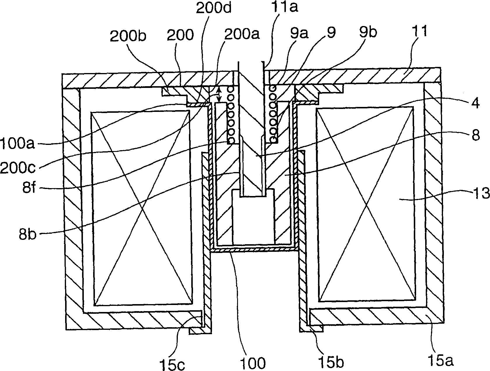
[0058] Figure 4 It is a side sectional view showing the main components of the electromagnetic switch device as the second embodiment of the present invention. Since the basic structure of the second electromagnetic switch device is the same as that of the conventional device, only the characteristic parts of the second electromagnetic switch device are described here. In particular, the second electromagnetic switch device including the sealed contact device is different from the conventional electromagnetic switch device 1000 including the conventional sealed contact device in that: Figure 21 The fixed iron core 7; is provided with a cylindrical member 100 made of magnetic material and has a closed bottom instead of Figure 21 The cylindrical member 10 made of a non-magnetic material is shown; a metal plate 300 made of a non-magnetic material is provided between the cylindrical member 100 and the first joining member 11; and the various components are mutually connected by la...

no. 3 example

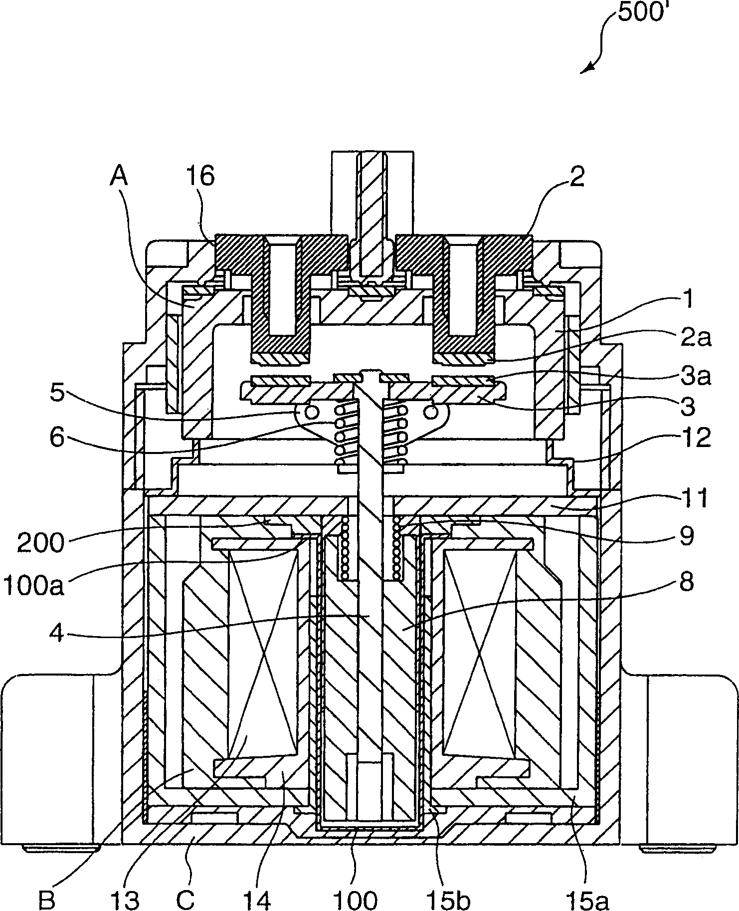
[0064] Figure 5 to Figure 8 It is an electromagnetic switch device as the third embodiment of the present invention. Figure 5 with Figure 6 These are a front cross-sectional view and a side cross-sectional view showing the third device, respectively. Figure 7 It is a top cross-sectional view of the coil. Figure 8 It is a circuit diagram illustrating the circuit used in the third device.

[0065] The third electromagnetic switchgear 501 including a sealed contact device includes: a sealed container 1 made of insulating material; fixed terminals 2, 2 having fixed contacts 2a, 2a to be airtightly joined to the sealed container 1; Contacts 2a, 2a movable movable contact piece 3; movable iron core 8 movable in one direction; cylindrical member 10 having a closed bottom for placing the movable iron core 8 therein; airtightly joined to The first engaging member 11 on the cylindrical member 10; the movable shaft 4 connected to the movable iron core 8; the movable contact 3a, 3a is p...


PUM


Abstract

In an electromagnetic switching device including a cylindrical part made of a magnetic material with a closed bottom for housing a movable iron core having a movable contact and so constructed as to render the movable contact movable toward and away from a fixed contact, a joint member made of a metallic material with an insertion hole formed substantially in the center thereof for movably receiving a movable shaft fixedly attached to the movable iron core, and a metal plate made of a non-magnetic material with a hole formed substantially in the center thereof with the inner diameter substantially the same as the inner diameter of the cylindrical part, the cylindrical part and the joint member are air-tightly jointed to each other with the metal plate provided therebetween, and the movable iron core is housed in the cylindrical part with a clearance defined between the movable iron core and the joint member corresponding to a required stroke within which the movable contact contacts the fixed contact. This arrangement provides improvement in magnetic efficiency of electromagnet of the device. Accordingly, improved energy saving performance is accomplished as compared with a case of a conventional electromagnetic switching device.

Description

Technical field [0001] The invention relates to an electromagnetic switch device including a sealed contact device, which is suitable for use as a relay for power-driven loads. Background technique [0002] Such as Figure 21 As shown, it proposes an electromagnetic switch device 100 including a sealed contact device, which is disclosed in Japanese Patent No. 3107288 (corresponding to Japanese Unexamined Patent Publication No. 9-259728). The structure of the device 1000 is that the relay contact part is placed in a closed or airtight space. With this configuration, since there is no possibility that the arc generated when the contact device is opened will leak to the outside of the equipment, this configuration does not require the space for the leaked arc that is necessary in the air conversion equipment, and can also reduce Each component is in close contact with the device to increase packaging density. The device 1000 is constructed as follows. [0003] Refer to Figure 21 , ...

Claims


Application Information

Patent Timeline
Patent Type & Authority Applications(China)
IPC IPC(8): H01H47/06H01H47/08H01H50/02H01H50/20H01H50/22H01H50/36H01H50/44H01H50/54H01H51/28
CPCH01H50/20H01H47/08H01H50/36H01H50/546H01H50/443H01H47/06H01H50/023H01H51/28H01H2050/025H01H50/22H01H50/54
Inventor 鱼留利一榎本英树山本律来往秀树
Owner MATSUSHITA ELECTRIC WORKS LTD
Why Eureka
Try Eureka