
Vehicle Brake, In Particular Caliper Brake

a technology of caliper brake and caliper head, which is applied in the direction of axially engaging brakes, brake actuating mechanisms, actuators, etc., can solve the problems of inability to maintain the parking brake state, the use of a threaded spindle with a self-locking thread and a large lead at first seems counterproductive to the requirement for low-power, etc., to achieve the effect of rapid realization and release of the parking brake sta

Inactive Publication Date: 2009-05-28
LUCAS AUTOMOTIVE GMBH
View PDF12 Cites 26 Cited by
  • Summary
  • Abstract
  • Description
  • Claims
  • Application Information

AI Technical Summary

Benefits of technology

[0003]A feature of the present invention is to provide a vehicle brake of the initially described type, which, while being of a simple and hence inexpensive construction, provides rapid realization and in particular release of the parking brake state.
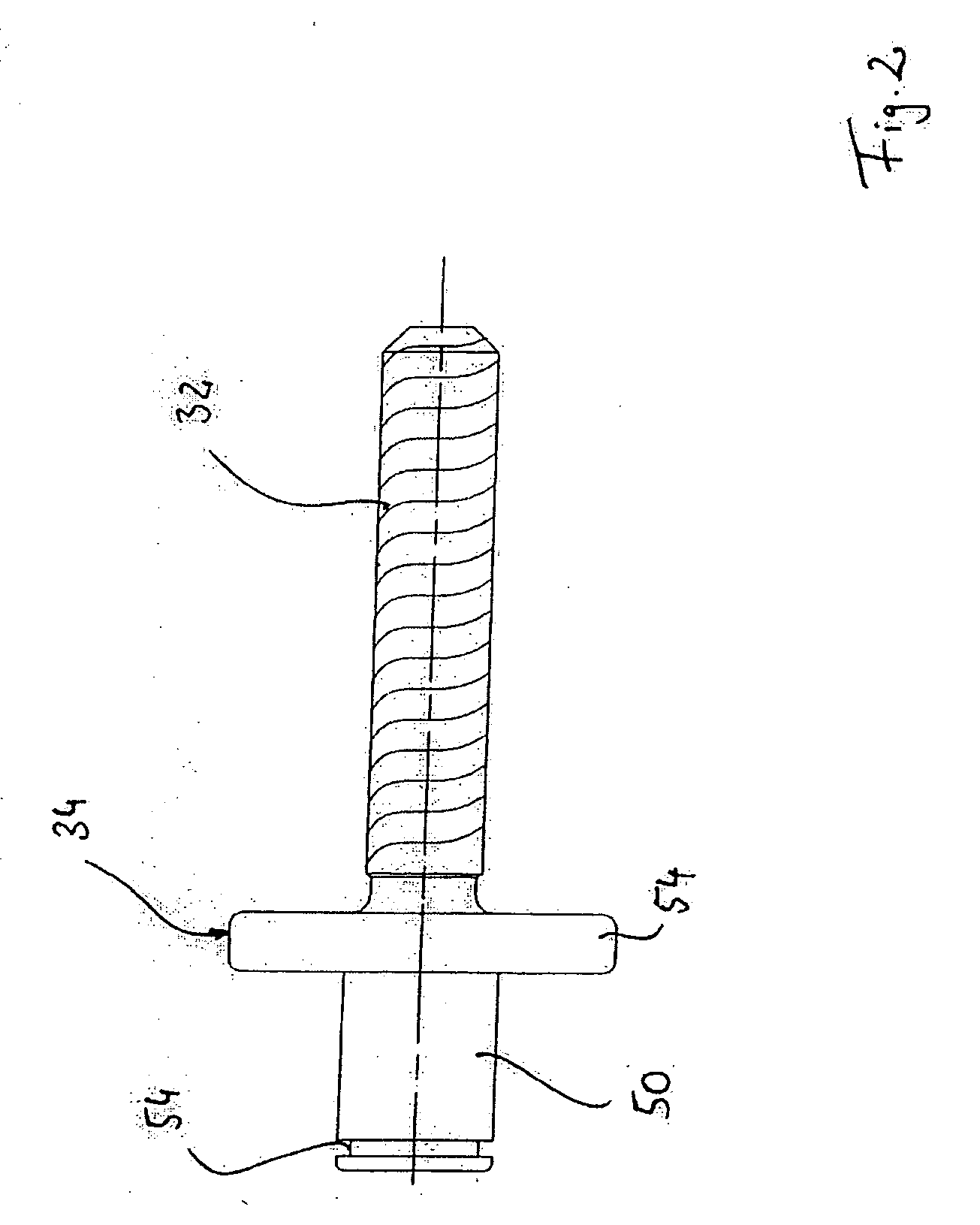
[0004]This feature is achieved by a vehicle brake of the initially described type, in which it is provided that the threaded spindle is provided with a self-locking thread having n flights, wherein the number n and the thread lead are selected in such a way that the thread is close to the self-locking limit. The use of a threaded spindle with a self-locking thread and a large lead at first seems counterproductive to the requirement for a low-power and hence inexpensively designed motorized drive. For the rule is namely that, given a constant clamping force (for example 15 Kn), the necessary torque (and hence the necessary motor output) rises if the spindle lead is increased. If, however, when effecting the parking brake operation the substantial displacement of the brake piston is effected hydraulically, so that the threaded spindle merely has to be displaced, substantially without opposed force, into an arresting position, then it is also possible to use a low-power drive for the threaded spindle because by means of the threaded spindle as such no application, or only a slight application of the brake piston occurs. Furthermore, the release of the parking brake state by means of a threaded spindle designed with a larger lead is considerably easier because in this way the self-locking may be overcome more easily.
[0008]As has already been mentioned above, according to the invention it may be provided that, for realizing an, in particular, high parking brake force, the brake piston is displaceable by charging the hydraulic chamber and in the displaced state the nut arrangement is displaceable into a blocking position by means of the threaded spindle. It may further be provided that, for cancelling the parking braking effect, the brake piston by driving the threaded spindle or the nut arrangement is displaceable out of the blocking position. This is particularly easy because of the large thread lead. Additional hydraulic assistance is therefore no longer required for cancelling the parking brake state.

Problems solved by technology

The use of a threaded spindle with a self-locking thread and a large lead at first seems counterproductive to the requirement for a low-power and hence inexpensively designed motorized drive.
The governing factor is however that the thread is still of a self-locking design, because otherwise the parking brake state cannot be maintained.

Method used


Image

  • Vehicle Brake, In Particular Caliper Brake
  • Vehicle Brake, In Particular Caliper Brake
  • Vehicle Brake, In Particular Caliper Brake

Examples


Embodiment Construction

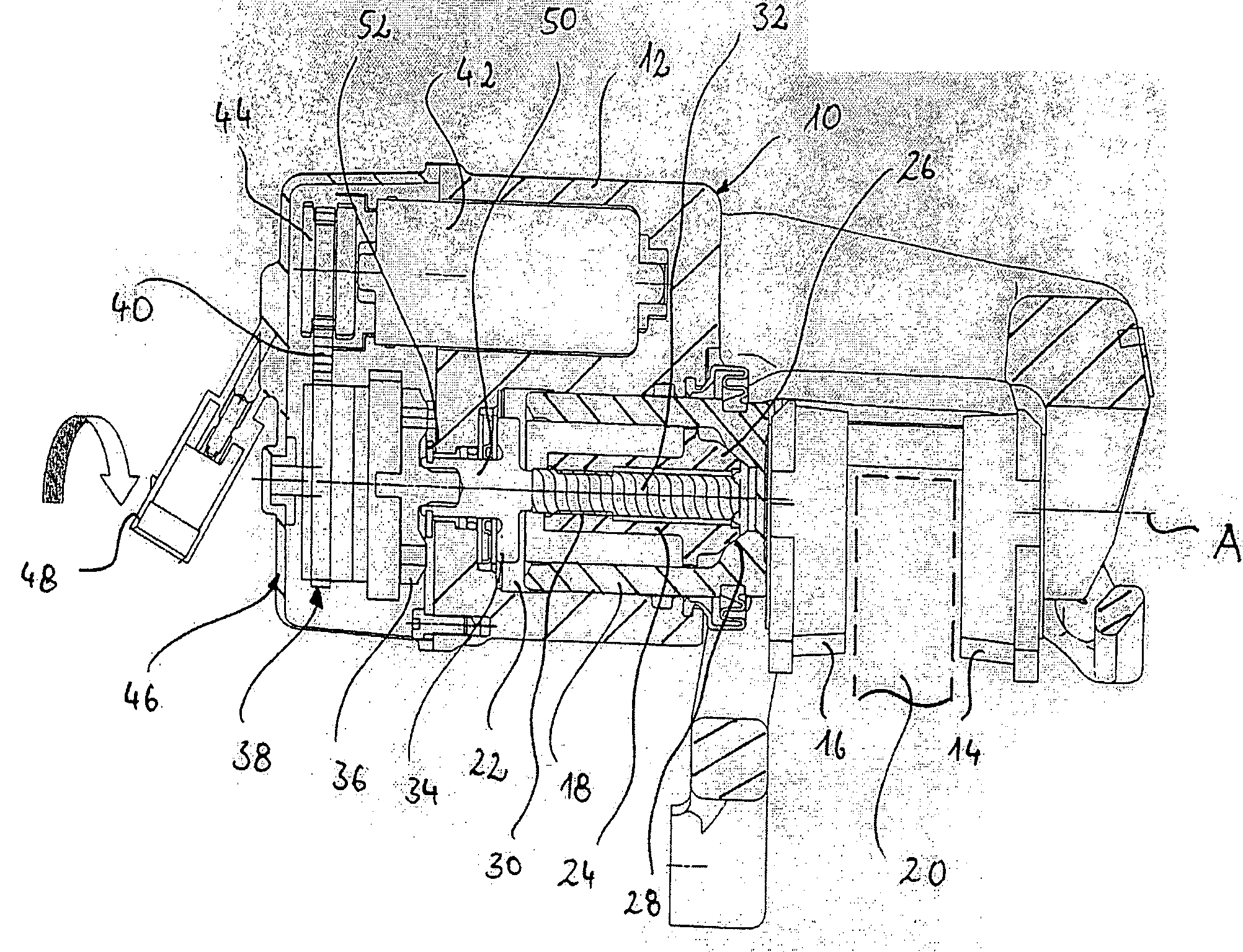
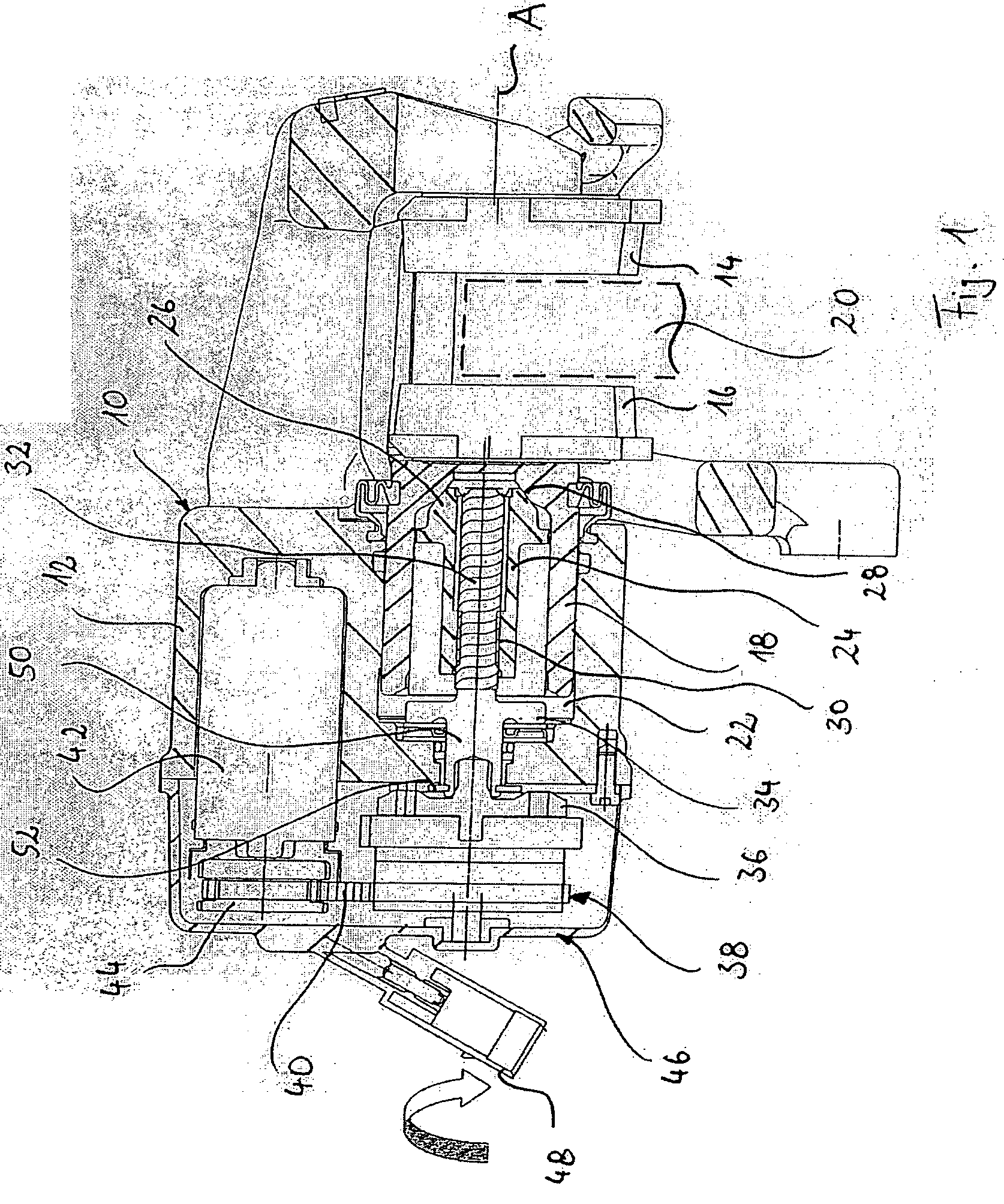
[0015]In FIG. 1 a vehicle brake according to the invention is denoted generally by 10. The vehicle brake 10 takes the form of a caliper brake. It comprises a housing 12, in which two brake linings 14 and 16 are accommodated in accordance with the floating caliper principle. The brake lining 16 is displaceable by means of a brake piston 18 along an axis A towards a brake disk 20, which is indicated merely by a dashed line.

[0016]The brake piston 18 with the housing 12 encloses a hydraulic chamber 22. The brake piston 18 is of a hollow design. Accommodated in the brake piston 18 is a nut arrangement 24, which has a conical head portion 26. The conical head portion 26 may be brought into blocking engagement with a conical portion 28 of a complementary design in the interior of the brake piston 18. The nut arrangement 24 is moreover accommodated in a rotationally fixed manner in the linearly displaceable brake piston 18. The nut arrangement 24 is likewise of a hollow design and is provid...


PUM


Abstract

The invention relates to a vehicle brake, in particular a caliper brake, having a housing, a brake piston accommodated in and linearly displaceable relative to the housing for displacing a brake lining, and a mechanical actuator arrangement for displacing the brake piston, wherein the brake piston is displaceable in the housing by charging a hydraulic chamber by means of a hydraulic brake circuit and wherein the mechanical actuator arrangement comprises a threaded spindle, which is mounted rotatably in the housing and may be set in rotation, wherein the brake piston as a result of a rotational movement of the threaded spindle is linearly displaceable relative to the housing. In this vehicle brake, it is provided that the threaded spindle is provided with a multiple-start self-locking thread having n flights, wherein the number n and the thread lead are selected in such a way that the thread is close to the self-locking limit.

Description

CROSS-REFERENCE TO RELATED APPLICATIONS[0001]This application is a National Stage of International Application No. PCT / EP2006 / 009408 filed Sep. 27, 2006, the disclosures of which are incorporated herein by reference in their entirety, and which claimed priority to German Patent Application No. 10 2005 046 140.9 filed Sep. 27, 2005, the disclosures of which are incorporated herein by reference in their entirety.BACKGROUND OF THE INVENTION[0002]The present invention relates to a vehicle brake, in particular to a caliper brake, having a housing, a brake piston accommodated in and linearly displaceable relative to the housing for displacing a brake lining, and a mechanical actuator arrangement for displacing the brake piston, wherein the brake piston is displaceable in the housing by charging a hydraulic chamber by means of a hydraulic brake circuit and wherein the mechanical actuator arrangement comprises a threaded spindle, which is rotatably mounted in the housing and may be set in r...

Claims


Application Information

Patent Timeline
IPC IPC(8): F16D65/16F16D65/18
CPCB60T13/741F16D65/18F16D2121/02F16D2129/10F16D2123/00F16D2125/40F16D2127/06F16D2121/24
Inventor GILLES, LEO
Owner LUCAS AUTOMOTIVE GMBH
Learn More