Moving picture coding apparatus

a coding apparatus and moving picture technology, applied in the field of bit rate control of moving picture coding apparatus, can solve the problems of data transmission delay, inability to reproduce moving picture data in real time, and inability to quickly produce data, so as to achieve the effect of bit rate control and rapid production

Inactive Publication Date: 2007-02-06
PANASONIC CORP
View PDF22 Cites 4 Cited by
  • Summary
  • Abstract
  • Description
  • Claims
  • Application Information

AI Technical Summary

Benefits of technology

[0028]Accordingly, in the moving picture coding apparatus, bit rate control can be quickly conducted according to the desired bit rate without decoding the input moving picture data, by replacing the P-frame of the input moving picture data with the I-frame whose bit amount is different and which is the rate correction data.
[0029]Eighthly, the moving picture data producing apparatus produces moving picture data. Said moving picture data is an input of the moving picture coding apparatus. The moving picture data producing apparatus is provided with a means for: determining the select and remove area in each frame; and for producing the rate correction data by which the rate correction is possible for at least more than one area in each selected and removed area in the frames. The moving picture data producing apparatus is further provided with a motion compensation means for inhibiting the motion estimation outside of the areas having the rate correction data in the preceding frame at the time of motion compensation and the select and remove areas. When one portion in the frame is selected and removed from the previously coded moving picture data and the new moving picture data is produced according to the desired bit rate, by selecting the data whose bit amount is different, the bit rate is controlled and the moving picture data can be quickly produced without decoding the moving picture data. Further, because motion estimation is not conducted outside of the selected and removed area, even by using only the selected and removed area of a portion of the frame, the decoding can be conducted without generating the motion compensation error.

Problems solved by technology

If the bit rate of the moving picture data is high, when the moving picture is transmitted at that rate, there is a problem in that delay is generated in the reception data, and the moving picture data cannot be reproduced in real time.
As described above, when the moving picture data is transmitted through various reception terminal equipment and transmission paths, it is necessary that the bit rate of the moving picture data be changed by adjusting to various bit rates, and a delay is generated in the data transmission by a time period for the processing of the rate control.
Further, when the VOD server sends out a plurality of moving picture data to a plurality of terminal equipment, as in the case of the VOD, the quantity of simultaneous connected terminal equipment is limited.
This is because excessive rate control processing is required, burdening the VOD server.
However, in this method, excessive processing is required because the moving picture data is decoded and coded again.
In addition, it is difficult to quickly change the bit rate and produce the moving picture data.
That is, because the moving picture data is decoded and coded again until the inverse quantization processing, the calculation load is large and it is difficult to quickly conduct the rate control.
Then, when the moving picture data includes the frame on which interframe predictive coding is conducted, a problem exists when the re-quantization is conducted by using the moving picture coding apparatus.
That is, for moving picture data on which inter-frame predictive coding has been conducted, when the moving picture data is produced by using the moving picture coding apparatus 5001, image quality deterioration is caused due to the motion compensation error.
Further, in order to prevent the image quality deterioration, it is necessary that the frame next to the frame on which the re-quantization is conducted, is re-corded including the motion compensation, and there is a problem that the processing time is further increased.
Accordingly, it is difficult to quickly produce the moving picture data.
When the conventional moving picture coding apparatus is used and the rate is controlled by performing the re-quantization, it is difficult to conduct the rate control without causing the image quality deterioration in the next frame on which the re-quantization is conducted.
This is due to motion compensation error.

Method used


Image

  • Moving picture coding apparatus
  • Moving picture coding apparatus
  • Moving picture coding apparatus

Examples


embodiment 1

[0069]In the first embodiment, a moving picture coding apparatus for performing data rate control without decoding previously compressed and coded moving picture data, and the new moving picture data produced, and its method will be described below.

[0070]Initially, the moving picture data producing apparatus which previously produces the moving picture data which is an input of the moving picture coding apparatus, will be described below.

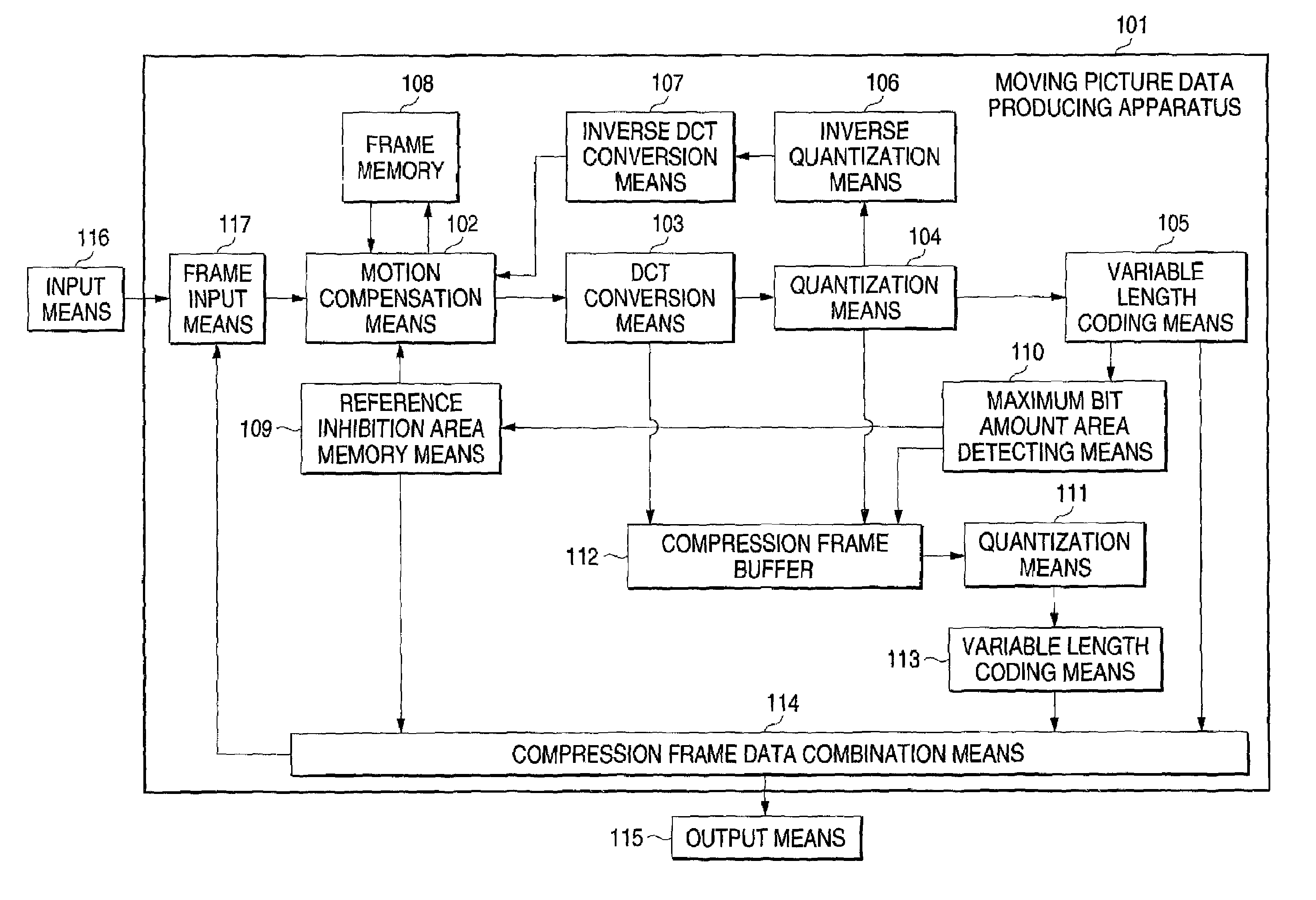
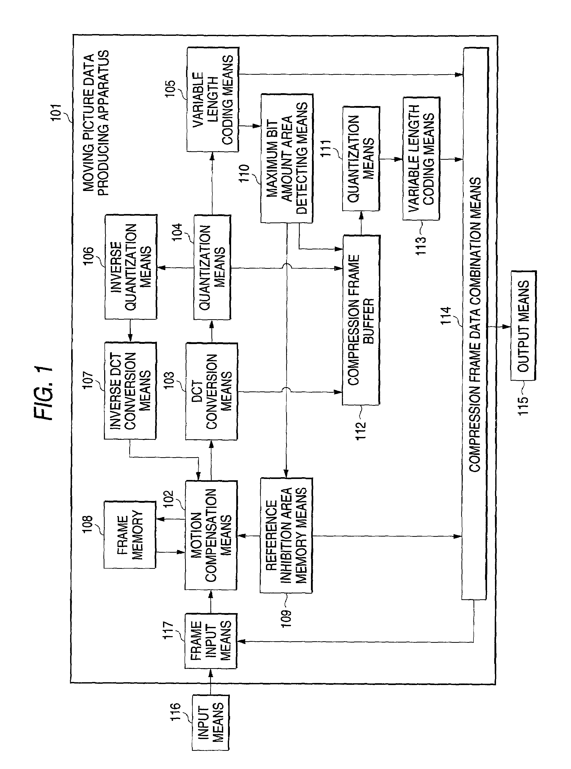
[0071]FIG. 1 shows the structure of the moving picture data producing apparatus to produce the moving picture data having the data structure to quickly conduct the rate control.

[0072]In FIG. 1, a moving picture data producing apparatus 101 is provided with a frame input means 117 connected to an input means 116; motion compensation means 102; DCT conversion means 103; quantizing means 104; variable length coding means 105; inverse quantizing means 106 to conduct the decoding; inverse DCT conversion means 107; and a frame memory 108 to store the deco...

embodiment 2

[0100]The second embodiment will be discussed below. It is an apparatus for performing rate control without decoding coded moving picture data, and further characterized in that, for the area selection method to produce the rate correction data, the known area to which likelihood of reference at the time of motion estimation is low, is used.

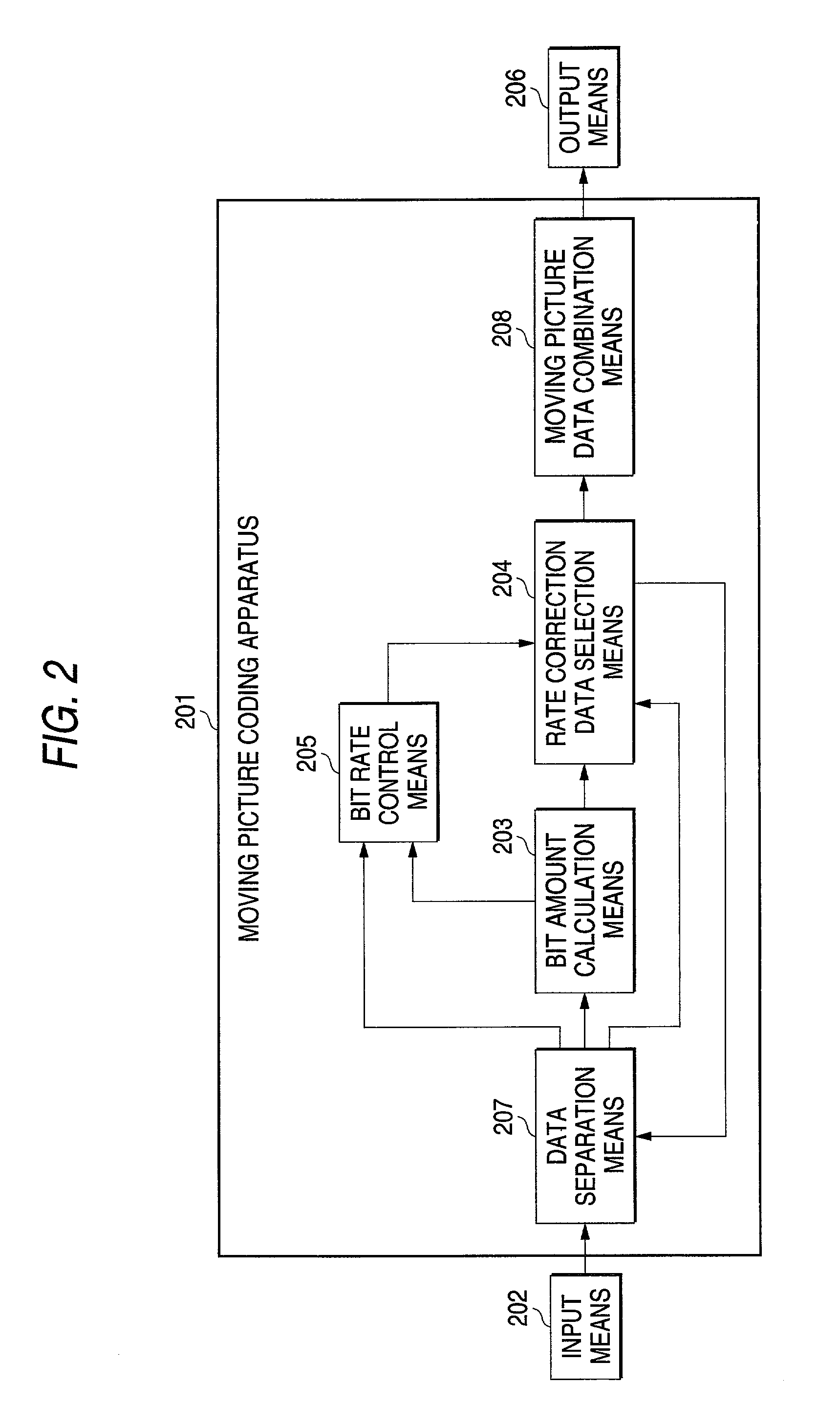
[0101]In the present embodiment, the moving picture coding apparatus 201, and the moving picture data it produces, are the same as in Embodiment 1.

[0102]A moving picture data producing apparatus for producing moving picture data, which is an input to the moving picture coding apparatus, will be described below.

[0103]In FIG. 3, the structure of the moving picture data producing apparatus 301, is shown. The apparatus produces moving picture data structured for quick performance of rate control.

[0104]In FIG. 3, the moving picture data producing apparatus 301 is provided with: a frame input means 117 connected to an input means 116; motion compensati...

embodiment 3

[0115]In the third embodiment, described below, the moving picture data producing apparatus has, by using the referred degree at the time of the motion estimation, a means for selecting the rate correction area to produce a plurality of data in which the bit amount is different.

[0116]Further, in the present embodiment, the moving picture coding apparatus is the same as in Embodiment 1.

[0117]The structure of the moving picture data producing apparatus is shown in FIG. 4. In FIG. 4, a moving picture data producing apparatus 401 has: a frame input means 117 connected to an input means 116; motion compensation means 402; DCT conversion means 103; quantization means 104; variable length coding means 405; inverse quantization means 106 for decoding; inverse DCT conversion means 107; frame memory 108 for storing the decoded frame; a referred area memory means 410 connected to a motion compensation means 402; and a rate correction area selection means 412; a compression frame buffer 112 con...


PUM


Abstract

An apparatus for compressing an uncompressed motion picture to generate compressed motion picture data, and also for generating and including rate correction data to be used by another apparatus to change the bit rate of the compressed motion picture data without decoding all of the encoded packets in the compressed motion picture data.

Description

BACKGROUND OF THE INVENTION[0001]The present invention relates to a bit rate control method for a moving picture coding apparatus to produce the moving picture data in which the bit rate is different from the compression coded moving picture data.[0002]Recently, according to the development of the digital signal processing engineering, moving picture data can be compressed and coded, and the compression and coded moving picture data is easy to handle. Further, with the development of a computer network, the compressed and coded moving picture data are increasingly transmitted and received through various transmission paths. For example, as a TV broadcasting station, a large amount of the moving picture data previously accumulated, is compression coded and saved, and as a VOD (Video On Demand), at the need of the user, the compressed and coded moving picture data can be transmitted onto the transmission path.[0003]However, where the compressed and coded moving picture data is transmi...

Claims


Application Information

Patent Timeline
Patent Type & Authority Patents(United States)
IPC IPC(8): H04N7/12H04N19/50G06T9/00H03M7/30H04N19/102H04N19/115H04N19/137H04N19/149H04N19/169H04N19/172H04N19/40H04N19/423H04N19/46H04N19/503H04N19/51H04N19/543H04N19/593H04N19/61H04N19/625H04N19/70H04N19/91
CPCH04N19/105H04N19/176H04N19/70H04N19/147H04N19/172H04N19/90H04N19/115H04N19/61H04N19/152H04N19/48H04N19/40H04N19/149
Inventor HONDA, YOSHIMASAKOMIYA, DAISAKUUENOYAMA, TSUTOMU
Owner PANASONIC CORP
Why Eureka
Try Eureka