
Healing components for use in taking impressions and methods for making the same

Inactive Publication Date: 2008-09-16
BIOMET 3I LLC
View PDF127 Cites 62 Cited by
  • Summary
  • Abstract
  • Description
  • Claims
  • Application Information

AI Technical Summary

Benefits of technology

[0013]According to the invention, the presence or absence of the markers in the marking locations may eliminate the need for an impression coping within the implant system. An impression can be taken of the mouth with the markers creating features in the impression material. The impression or a model of the impression is read or scanned such that the markers indicate various characteristics of the healing abutment and also the implant. Further, such a system eliminates the need to remove the healing abutment until the permanent components are ready to be installed in the patient's mouth.
[0014]Specifically, the presence or absence of the binary-coded markers in the marking locations allow the dentist to determine various physical characteristics, such as the healing abutment height, healing abutment diameter, dimensions of the attached implant seating surface, and the orientation of the implant's fitting. It is contemplated in accordance with one embodiment of the present invention that these marking locations containing the binary-coded markers are preferably located on the top of the healing abutment, although it may be possible to place some markers on the side of the healing abutment.
[0017]An impression of the mouth is taken with the inventive healing abutment mounted on the implant. The impression process creates a “negative” image of the information markers in the impression material that change the physical shape of the top or side surface. A corresponding mold is created from the impression. This mold, or a stone model created from the mold, can then be scanned. A computer program is able to create a three-dimensional perspective of the relevant jaw section of the patient, including the implant and abutment. Due to the information markers on the surface of the healing abutment now present in the mold, the computer program is able to accurately analyze and produce the appropriate dimensions of the aperture in the gingiva and the orientation of the underlying hexagonal boss of the implant so that a clinician can instruct a milling machine to produce the permanent components.
[0018]In an alternative embodiment, the scanner simply takes the necessary information directly from the mouth of a patient without the need for impression material whatsoever. The information markers of the healing abutment provide the required information of the gingival aperture and the orientation of the underlying hexagonal boss on the implant. If a laser or photographic scanning system is used, the etched markers are identified just as easily as the markers that change the physical shape of the healing abutment.
[0019]This system allows the dentist to produce the permanent components more quickly because the healing abutment does not have to be removed in order to produce the permanent dental components. In other words, the second step of taking an impression with an impression coping is eliminated. The dentist also does not have to confront the difficulties of gingival closure that appear when a healing implant is removed. Finally, the patient is not forced to endure the somewhat painful procedure of healing abutment removal. With the procedure of the present invention, the removal of the healing abutment can occur during the same surgery as the installation of the permanent components.

Problems solved by technology

Otherwise, a less than accurate impression of the condition of the patient's mouth is taken.

Method used


Image

  • Healing components for use in taking impressions and methods for making the same
  • Healing components for use in taking impressions and methods for making the same
  • Healing components for use in taking impressions and methods for making the same

Examples


Embodiment Construction

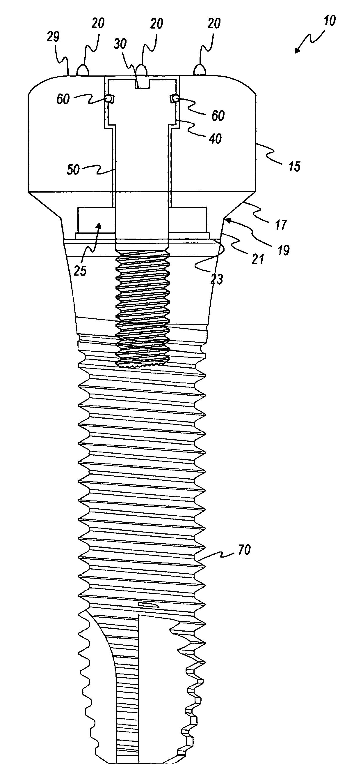
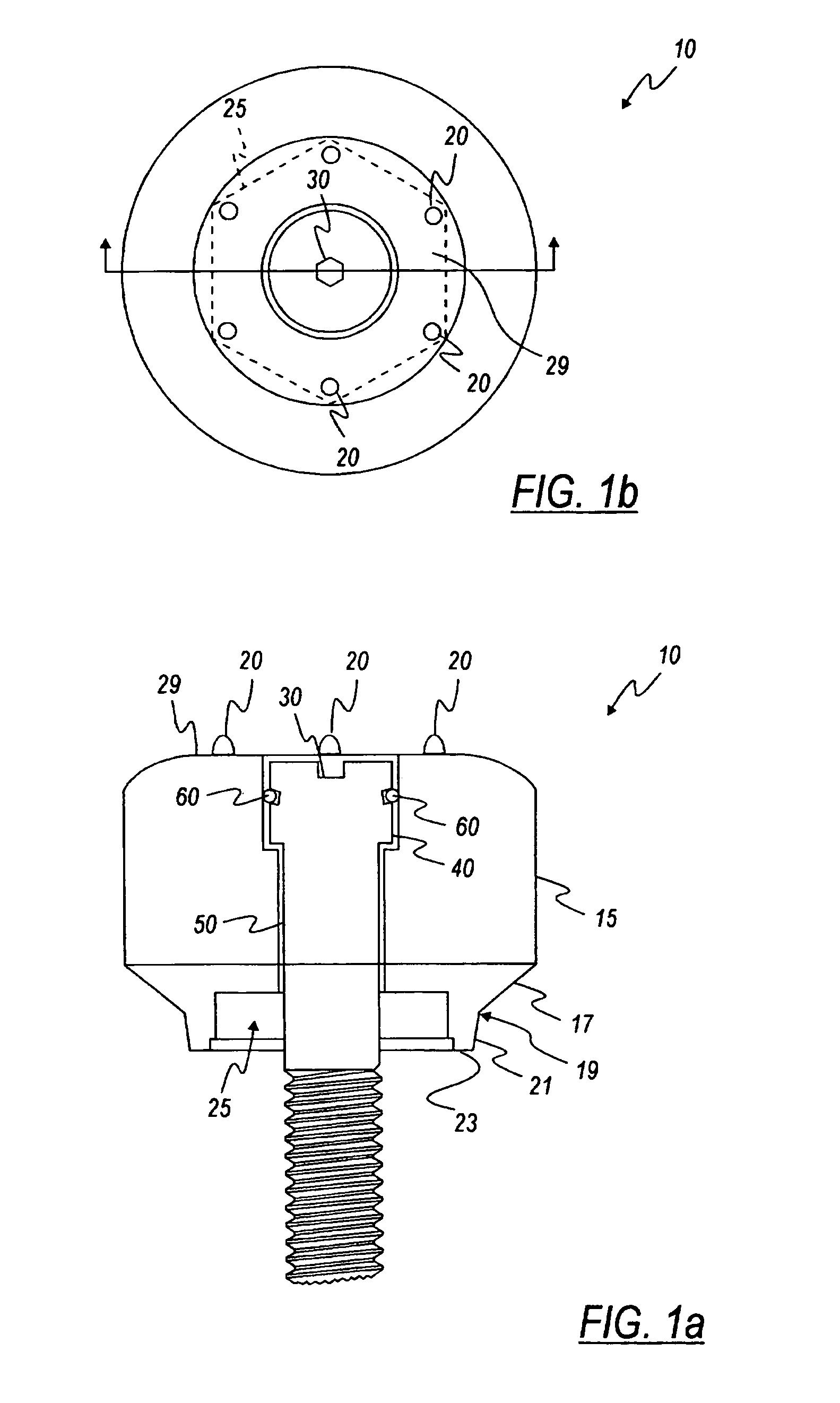
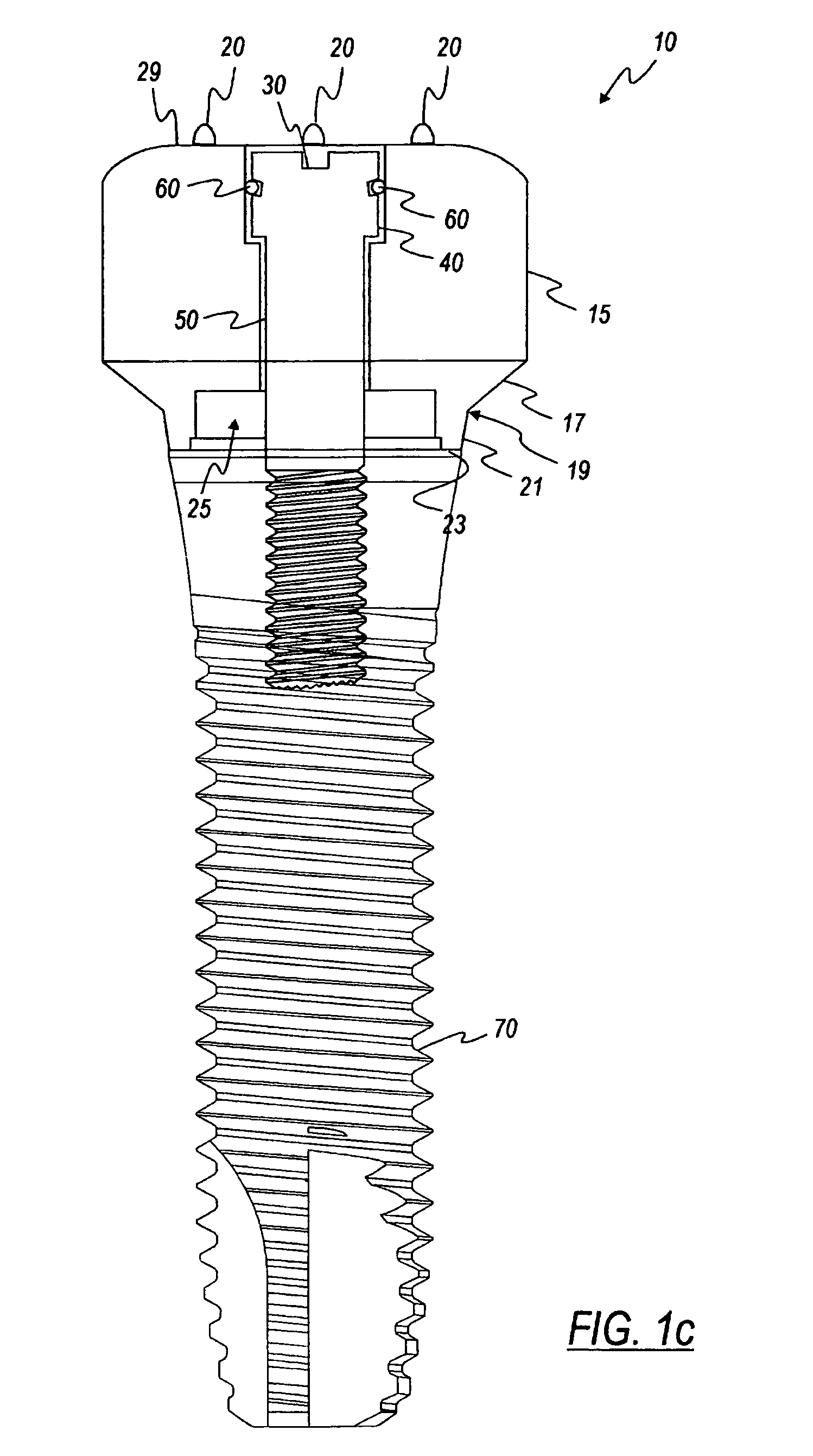
[0041]As shown in FIGS. 1a and 1b, the healing abutment 10 of one embodiment of the present invention has a main body 15 with a generally circular cross-sectional shape, a first tapered section 17, a boundary 19, a second tapered section 21, an end surface 23, a hex socket 25, and dimensions that are generally suitable for replicating the emergence profile of a natural tooth. The first tapered section 17 extends downward from the main body 15 of the abutment 10, having a diameter at a boundary 19 that is generally larger than the implant (not shown). The boundary 19 separates the first tapered section 17 from the second tapered section 21 that terminates in the end surface 23. The second tapered section 21 is at an angle with the central axis of the implant that is generally in the range of from about 5° to about 15°, with 10° being preferable. Alternatively, the second tapered section 21 may be omitted such that the first tapered section 17 tapers directly to the diameter of the en...


PUM


Abstract

The present invention provides a healing abutment for attachment to a dental implant with marking locations thereon. The marking locations either lack or have markers that provide a binary code system for retrieving unique information about the healing abutment and the underlying implant.

Description

CROSS-REFERENCE TO RELATED APPLICATIONS[0001]This is a continuation application of U.S. patent application Ser. No. 10 / 007,997, filed Nov. 13, 2001, now U.S. Pat. No. 6,790,040 which is a continuation-in-part of U.S. patent application Ser. No. 09 / 710,208, filed Nov. 10, 2000, now U.S. Pat. No. 6,558,162 which claimed the benefit of priority of U.S. patent application Ser. No. 60 / 164,521, filed Nov. 10, 1999.TECHNICAL FIELD OF INVENTION[0002]The present invention relates generally to a healing abutment in a dental implant system. More particularly, the present invention relates to the use of a binary marking system on the exterior of a healing abutment to identify unique characteristics of the healing abutment.BACKGROUND OF THE INVENTION[0003]The dental restoration of a partially or wholly edentulous patient with artificial dentition is typically done in two stages. In the first stage, an incision is made through the gingiva to expose the underlying bone. An artificial tooth root, u...

Claims


Application Information

Patent Timeline
IPC IPC(8): A61C8/00A61C13/08A61C9/00
CPCA61C8/0001A61C8/008A61C9/0053G06F17/50A61C13/08A61C13/083A61B1/24A61C13/0004A61C8/00G06F30/00A61C8/005A61C9/004
Inventor AMBER, JOHN T.PORTER, STEPHAN S.POWELL, THEODORE M.
Owner BIOMET 3I LLC
Learn More