Method for Optimizing the Cryogenic Pressure Tank Fill Level Which Can Be Achieved During a Refill in a Motor Vehicle

Inactive Publication Date: 2018-05-17
BAYERISCHE MOTOREN WERKE AG
View PDF0 Cites 1 Cited by
  • Summary
  • Abstract
  • Description
  • Claims
  • Application Information

AI Technical Summary

Benefits of technology

[0007]The object is achieved by a method for optimizing the filling level, which is able to be reached during a refilling procedure, of a cryogenic pressure tank in a motor vehicle, wherein a heating device for heating a gas in the pressure tank has at least two modes, namely a regular operation mode, in which the heating device heats the gas in the pressure tank such that a predefined pressure of the gas in the pressure tank is reached, and a continuous operation mode, in which the heating device heats the gas in the pressure tank continuously such that the pressure of the gas in the pressure tank rises beyond the predefined pressure. The method comprises the steps of: detecting the density of the gas in the pressure tank; comparing the detected density of the gas in the pressure tank with a predefined density value; and, if during the comparison it is determined that the detected density drops below the predefined density value, then, depending on at least one item of route information of the motor vehicle, in particular depending on a determined route to the destination of the motor vehicle and on the refueling stations for refilling the pressure tank with gas which are available on the determined route to the destination, either operating the heating device in the regular operation mode or switching the heating device from the regular operation mode into the continuous operation mode.
[0008]An advantage of said method is that the heating device is switched into the continuous operation mode (in addition) depending on the route information and is not only switched into the continuous operation mode depending on the density of the gas in the pressure tank. Consequently, in comparison with a conventional method, the continuous operation mode can be activated in a delayed manner or not at all, even if a predefined density is or has been undershot. Operating or leaving the heating device in the regular operation mode for a (longer) time results in the gas in the pressure tank remaining cold for longer. As a result, the reachable filling level of the pressure tank with gas, that is to say the quantity of gas which is kept available or stored in the pressure tank, is optimized or increased when or after a maximum possible refilling procedure is carried out. Consequently, the range of the motor vehicle increases after a refilling procedure is carried out. Depending on route information, a decision is made as to whether it is necessary to switch the heating device into the continuous operation mode in order thus to increase the (residual) range with the available gas in the pressure tank. Depending on the reachability of refueling stations, in particular gas refueling stations, on the way to the destination, that is to say refueling stations along the route to the destination and/or refueling stations which are able to be reached by means of a slight detour from the route to the destination, in comparison with conventional methods, the continuous operation mode is activated later or not at all (the heating device is then operated further in the regular operation mode, in this case). Consequently, the gas in the pressure tank remains cool(er) or has a lower temperature. Thus, when refilling the pressure tank (refueling), it is possible for a higher density of gas in the pressure tank or a higher filling level to be reached. As a result, after a (maximum) refilling procedure is carried out, which is determined inter alia by the maximum possible pressure in the pressure tank (before a safety valve opens), more gas is available after the refilling into the pressure tank.
[0009]According to a further embodiment, the decision as to whether the heating device is operated in the regular operation mode, or whether the heating device is switched from the regular operation mode into the continuous operation mode, is additionally dependent on a selected refueling management mode which is selectable from multiple different refueling management modes, wherein the different refueling management modes weight differently multiple goals, such as for example travel time of the motor vehicle to the destination, number of required refueling procedures for refilling the pressure tank until reaching the destination, maximum range of the motor vehicle with the gas in the pressure tank after a maximum possible refilling procedure of the

Problems solved by technology

In previously known methods concerning the switching of a heating device for heating the gas in the pressure tank from tank-heat-exchanger regular operation, in which the gas in the pressure tank is heated slightly (at intervals) in order to (re-)establish a predefined pressure, into tank-heat-exchanger continuous operation (THE continuous operation), in which the gas in the pressure tank is heated continuously in order to increase the residual range, it is a disadvantage that, as a result of activating the THE continuous operation, as soon as a predefined density of the gas in the pressure tank is undershot, the gas in the pressure tank and the pressure tank have an extremely high temperature during the next refill

Method used


Image

  • Method for Optimizing the Cryogenic Pressure Tank Fill Level Which Can Be Achieved During a Refill in a Motor Vehicle
  • Method for Optimizing the Cryogenic Pressure Tank Fill Level Which Can Be Achieved During a Refill in a Motor Vehicle
  • Method for Optimizing the Cryogenic Pressure Tank Fill Level Which Can Be Achieved During a Refill in a Motor Vehicle

Examples


Example

DETAILED DESCRIPTION OF THE DRAWINGS

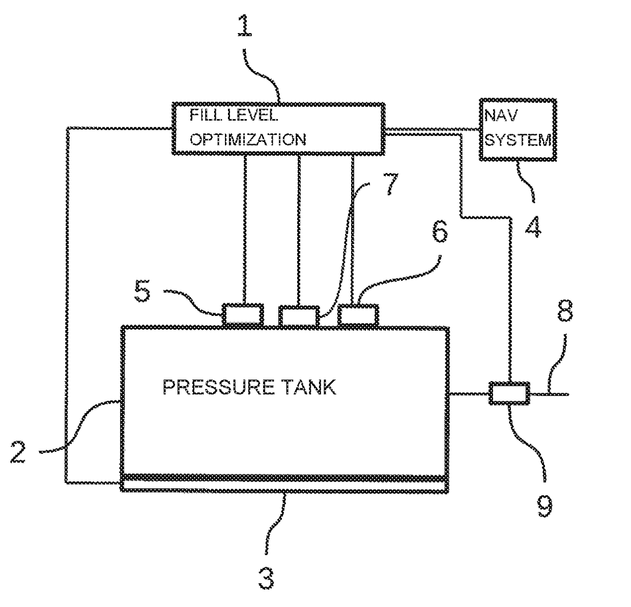
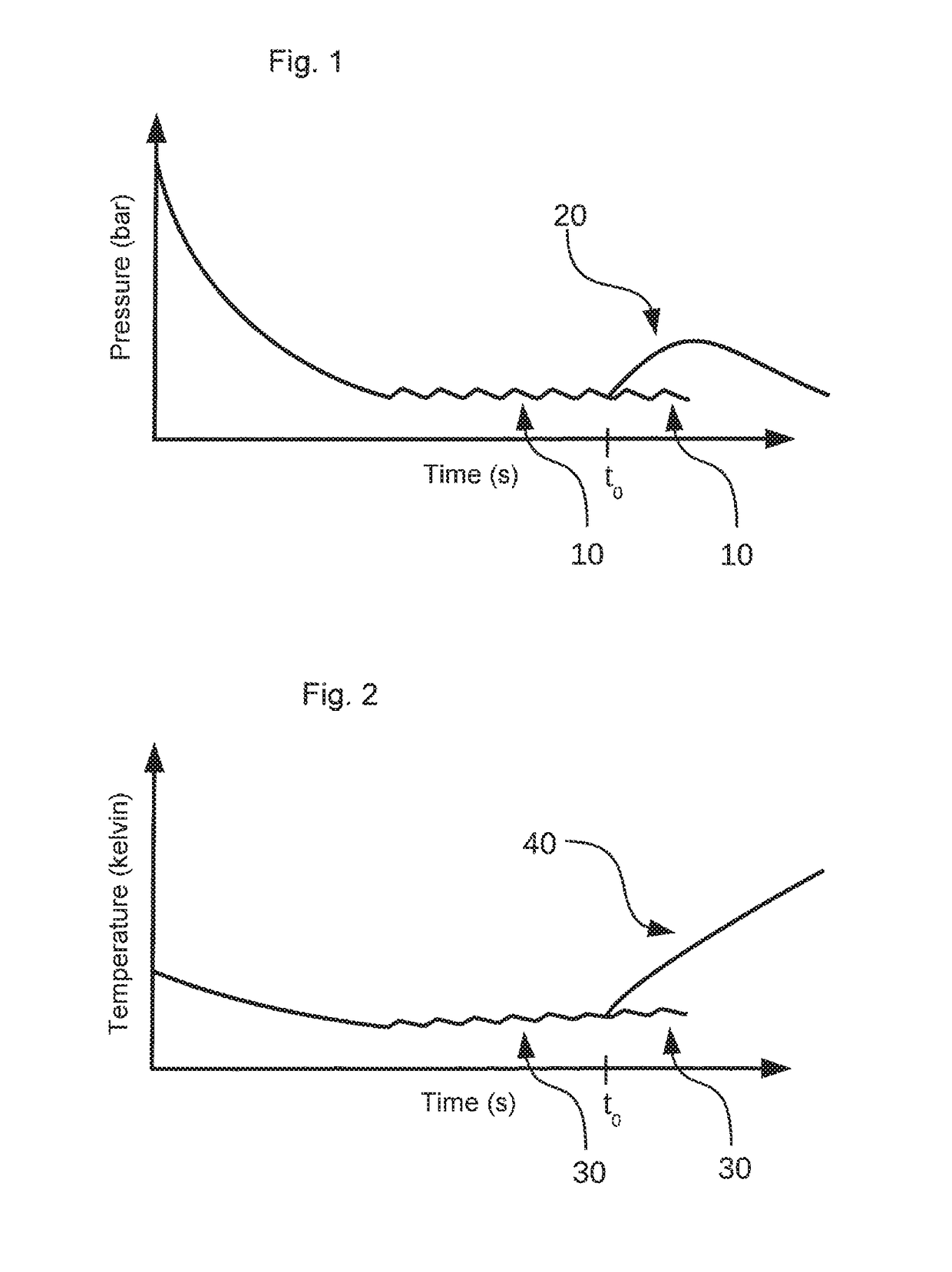
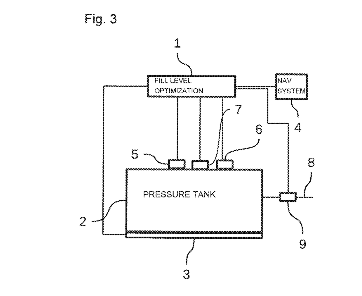
[0030]FIG. 1 shows a pressure-time diagram in which the pressure (measured in bar) is represented on the y-axis and the time (measured in seconds) is represented on the x-axis. In the region on the right in FIG. 1, the pressure profile is shown in the continuous operation mode 20, in which the pressure rises above the predefined pressure value. From point in time t0 onward, two alternatives are illustrated in FIG. 1. The upper line in the region on the right in FIG. 1 shows the pressure profile 20 if at the point in time t0 the heating device 3 is switched (due to the predefined density being undershot and in dependence on route information) from the regular operation mode into the continuous operation mode and is subsequently operated in the continuous operation mode. The lower line shows the pressure profile 10 if at the point in time t0 the heating device 3 is left in the regular operation mode or is operated in the regular operation mode. The ...


PUM


Abstract

A method optimizes the cryogenic pressure tank fill level which can be achieved during a refill in a motor vehicle. A heating device for heating a gas in the pressure tank has at least two modes, namely a regular operating mode, in which the heating device heats the gas in the pressure tank such that a specified pressure of the gas in the pressure tank is reached, and a continuous operation mode in which the heating device constantly heats the gas in the pressure tank such that the pressure of the gas in the pressure tank rises above the specified pressure. The method has the following steps: detecting the density of the gas in the pressure tank; comparing the detected density of the gas in the pressure tank with a specified density value; and if during the comparison it is determined that the detected density falls below the specified density value, either operating the heating device in the regular operating mode or switching the heating device from the regular operating mode to the continuous operation mode, in particular on the basis of a specified path to the destination of the motor vehicle and the service stations provided on the specified path to the destination for refilling the pressure tank with gas.

Description

CROSS REFERENCE TO RELATED APPLICATIONS[0001]This application is a continuation of PCT International Application No. PCT / EP2016 / 068500, filed Aug. 3, 2016, which claims priority under 35 U.S.C. § 119 from German Patent Application No. 10 2015 217 085.3, filed Sep. 7, 2015, the entire disclosures of which are herein expressly incorporated by reference.BACKGROUND AND SUMMARY OF THE INVENTION[0002]The technology disclosed herein relates to a method for optimizing the filling level, which is able to be reached during a refilling procedure, of a cryogenic pressure tank in a motor vehicle, to a filling level optimization device for optimizing the filling level which is able to be reached during a refilling procedure of a cryogenic pressure tank in a motor vehicle and to a pressure tank with such a filling level optimization device.[0003]Cryogenic pressure vessel systems are known from the prior art. They include cryogenic pressure vessels. Such a pressure vessel has an inner vessel and an...

Claims


Application Information

Patent Timeline
IPC IPC(8): G01C21/34B60K15/03
CPCG01C21/3469B60K15/03006G01C21/3626F17C9/02F17C13/023F17C13/025F17C13/026F17C2265/066F17C2270/0168F17C2270/0178F17C2270/0171F17C2221/012F17C2223/036F17C2223/035F17C2223/0115F17C2221/033F17C2250/0421F17C2250/0426F17C2250/0439F17C2250/0443F17C2250/043F17C2250/072F17C2250/0626F17C2250/0491F17C2250/0478F17C2260/02F17C2225/0161F17C2225/033F17C2227/0379F17C2227/0323F17C2227/0304F17C2227/0302F17C2250/03F17C2250/032F17C2227/0383Y02E60/32
Inventor STAHL, HANS-ULRICHMOVSISYAN, GEORG
Owner BAYERISCHE MOTOREN WERKE AG
Why Eureka
Try Eureka