
Magnetic resonance imaging method, residual magnetism quantity measurement method and magnetic resonance imaging device

A technology of magnetic resonance imaging and magnetic resonance imaging, which is applied in the direction of magnetic resonance measurement, measurement using nuclear magnetic resonance imaging system, measurement device, etc., can solve the problem of inability to suppress the influence, etc., to improve the image quality, suppress the influence, and reduce the residual magnetism. amount of effect

Inactive Publication Date: 2005-03-23
GE MEDICAL SYST GLOBAL TECH CO LLC
View PDF1 Cites 0 Cited by
  • Summary
  • Abstract
  • Description
  • Claims
  • Application Information

AI Technical Summary

Problems solved by technology

[0004] The above-mentioned conventional technology can suppress the influence of the residual magnetism within a pulse sequence, but cannot suppress the influence of the residual magnetism caused by the previous pulse sequence on the current pulse sequence

Method used


Image

  • Magnetic resonance imaging method, residual magnetism quantity measurement method and magnetic resonance imaging device
  • Magnetic resonance imaging method, residual magnetism quantity measurement method and magnetic resonance imaging device
  • Magnetic resonance imaging method, residual magnetism quantity measurement method and magnetic resonance imaging device

Examples


Embodiment Construction

[0053] The present invention will be specifically explained below with reference to the embodiments shown in the drawings. It should be appreciated that the present invention is not limited to these examples.

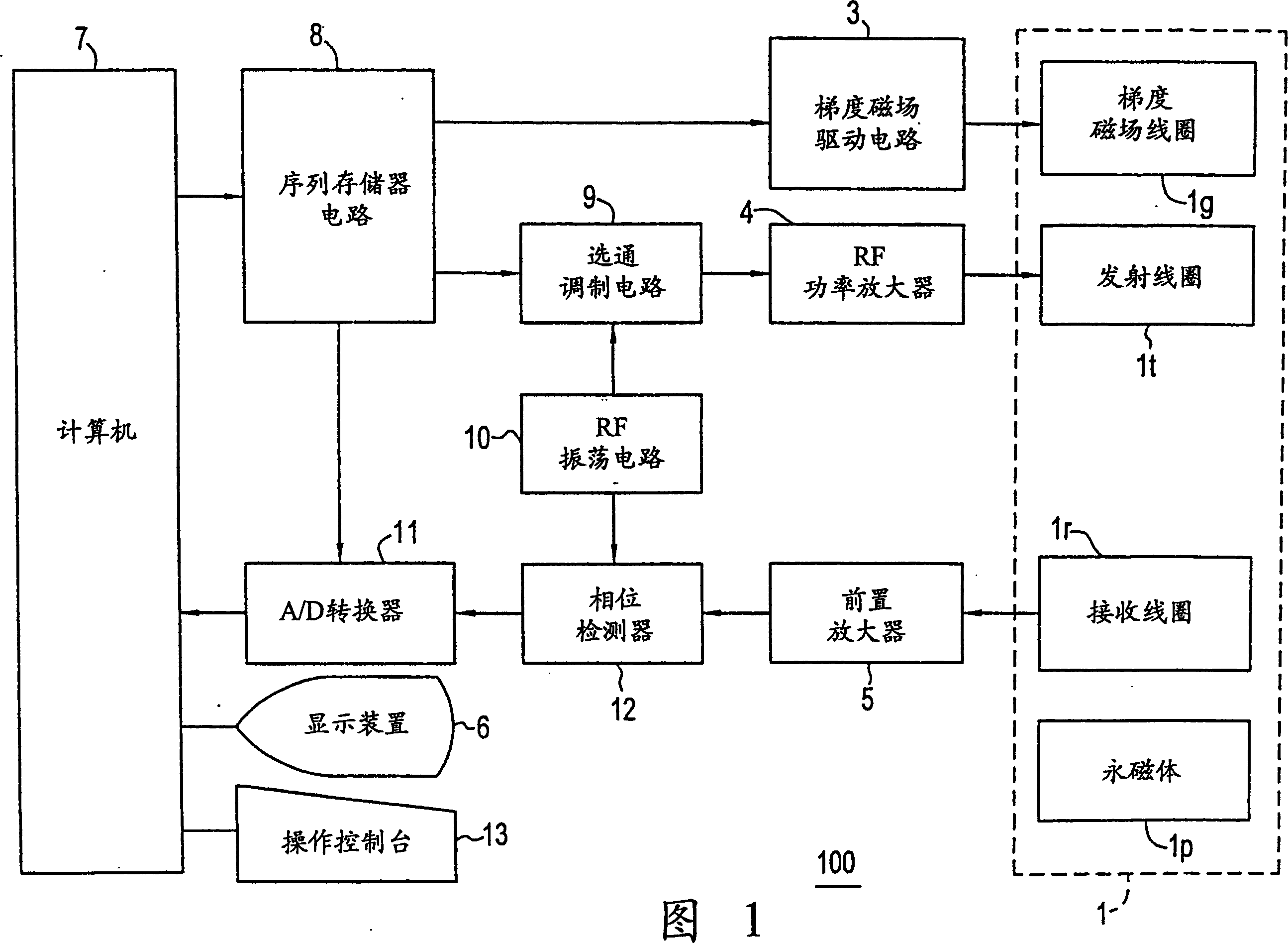
[0054] Fig. 1 is a block diagram of an MRI apparatus according to one embodiment of the present invention.

[0055] In the MRI apparatus 100, the magnetic member 1 has a hollow portion (bore) into which a source can be inserted, and a permanent magnet 1p is arranged around the hollow portion to apply a constant magnetic field to the source; -, a gradient magnetic field coil 1g for generating a gradient magnetic field in the Y- and Z-axes; a transmitting coil 1t for applying an RF pulse to excite the rotation of the nucleus in the source; and a receiving coil 1r for detecting an NMR from the source Signal. The gradient magnetic field coil 1g, the transmitting coil 1t, and the receiving coil 1r are connected to a gradient magnetic field drive circuit 3, an RF power ampl...


PUM


Abstract

MR imaging method, residual magnetizaton amount measuring method and MRI apparatus are disclosed. To suppress the influence of remanent magnetization caused by a previous pulse sequence for MR imaging to an MR image, Gradient pulse strings RS1 to RS4 for degaussing are applied, preceeding the pulse sequence for MR imaging in order to cancel remanent magnetization caused by a previous pulse sequence for MR imaging.

Description

technical field [0001] The present invention relates to a magnetic resonance (MR) imaging method, a method for measuring residual magnetism and a magnetic resonance imaging (MRI) device, in particular to a kind of MR imaging capable of suppressing the influence of the residual magnetism caused by the previous pulse sequence on the current pulse sequence method, a residual magnetism measuring method for checking degaussing effect, and an MRI apparatus for realizing these methods. Background technique [0002] MR imaging methods are disclosed in Japanese Patent Application Laid-Open Nos. H8-322817 and H10-75940. A correction component is added to the phase encoder or rewinding gradient to suppress the remanence caused by a phase encoder gradient to the phase. The influence of the echo following the one corresponding to the encoder gradient. [0003] In MR imaging, a pulse sequence consisting of transmitting an RF (radio frequency) pulse, applying a phase encoder gradient, and...

Claims


Application Information

Patent Timeline
Patent Type & Authority Patents(China)
IPC IPC(8): G01R33/48A61B5/055G01R33/561G01R33/565
CPCG01R33/565G01R33/56554A61B5/055
Inventor M·米约施
Owner GE MEDICAL SYST GLOBAL TECH CO LLC
Learn More