Switch device and steering switch apparatus equipped with the switch device

a technology of switch device and switch device, which is applied in the direction of emergency actuator, switch with three operating positions, contacts, etc., can solve the problems of increasing the height of the housing, difficult to achieve the low-profile structure of the entire device, and the aptness of the actuator to become, so as to achieve high assembly efficiency and reduce the height. , the effect of high assembly efficiency

Inactive Publication Date: 2008-10-21
ALPS ALPINE CO LTD
View PDF14 Cites 17 Cited by
  • Summary
  • Abstract
  • Description
  • Claims
  • Application Information

AI Technical Summary

Benefits of technology

[0012]According to the switch device described above, the drive portion of the operating member tilts the actuator, disposed adjacent to the operating member, in response to a rotating operation so that one of the ends of the actuator pushes the corresponding switch unit disposed below the end. Accordingly, since the actuator and the switch units are disposed adjacent to a side of the operating member, the housing is reduced in height, thereby facilitating a low-profile structure.
[0026]In a present embodiment, the opposite ends of the actuator are disposed on the corresponding protuberances of the rubber sheet in a manner such that each end is elastically in contact with the corresponding protuberance. Therefore, at an assembly stage, the actuator can be set in a preloaded state. This allows the actuator to be installed in the housing in a backlash-free positioned state, and prevents the rubber sheet from becoming displaced or detached by means of the ends of the actuator, whereby high assembly efficiency is achieved. Alternatively, the actuator is tiltably supported by the tiltably-supporting portion can be tilted readily in response to an oblique or lateral driving force. Accordingly, a highly versatile switch device that is at least readily applicable to various operating types is achieved.

Problems solved by technology

This leads to an increase in the height of the housing, which makes a low-profile structure for the entire device difficult to achieve.
The actuator is apt to become displaced or detached at an assembly stage, which is one of significant factors that lower the assembly efficiency.
In the conventional example, since the operating member has to be used for pushing the actuator downward, the operating method of the operating member is extremely limited.
For example, it is difficult to apply the conventional example to a switch device of a sliding type.

Method used


Image

  • Switch device and steering switch apparatus equipped with the switch device
  • Switch device and steering switch apparatus equipped with the switch device
  • Switch device and steering switch apparatus equipped with the switch device

Examples


Embodiment Construction

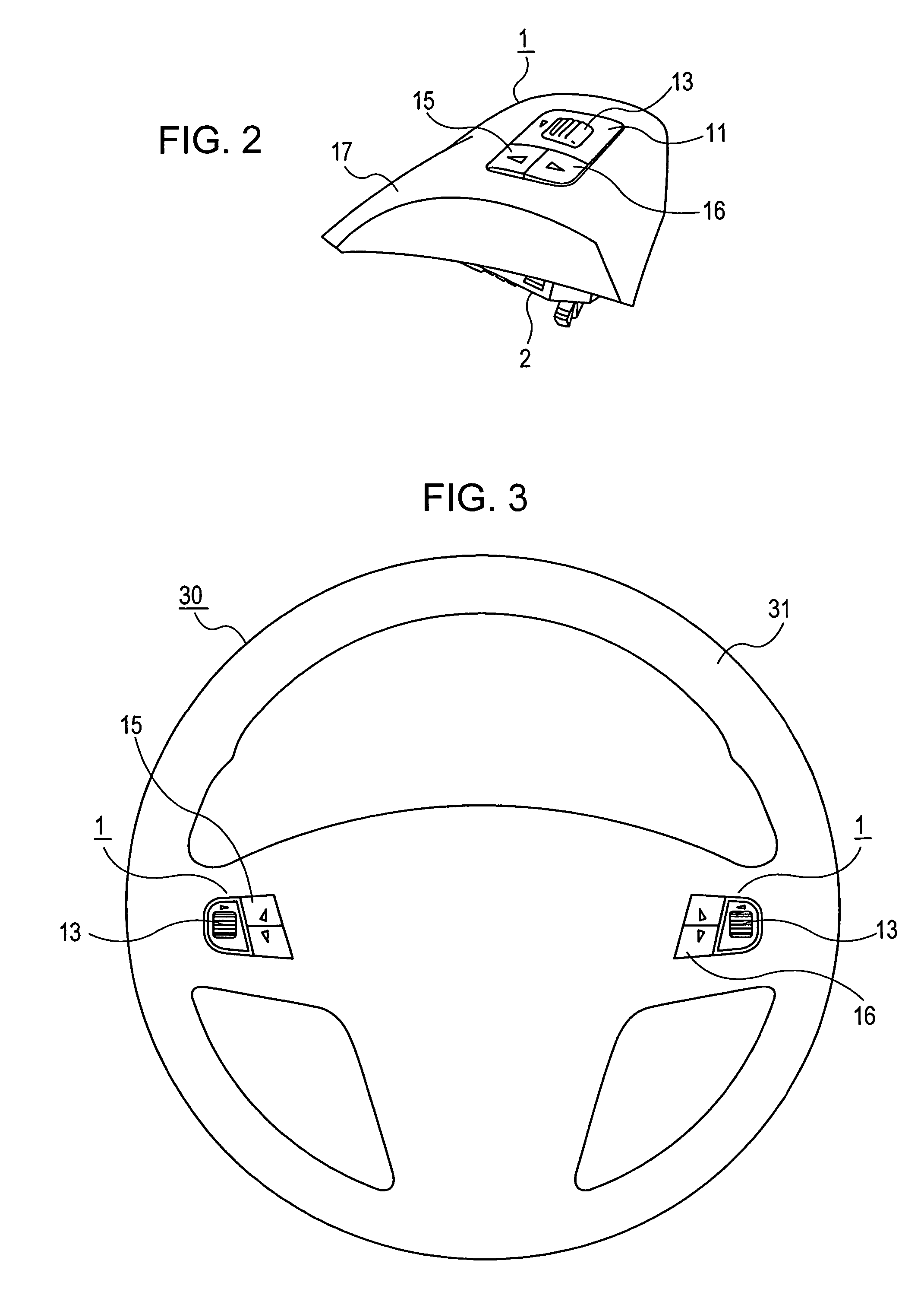
[0034]FIG. 3 illustrates a steering switch apparatus which includes a pair of left and right switch devices 1 according to an embodiment disposed within a circular ring portion 31 of a steering wheel 30 of a vehicle. The pair of steering devices 1 is bisymmetrical to each other, and the basic structure between the two is substantially the same. Therefore, the description below will only refer to the switch device 1 disposed on the right side of FIG. 3.

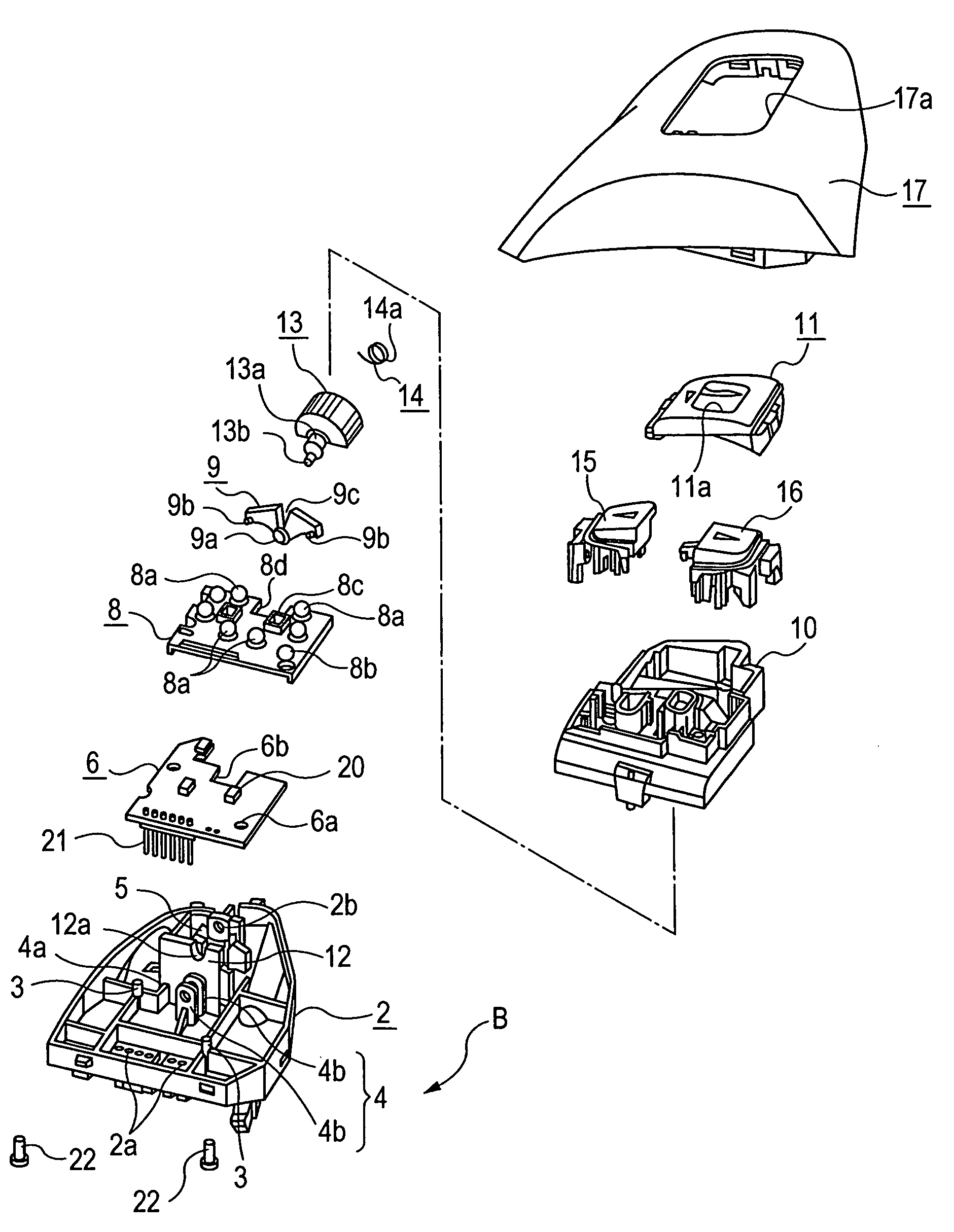
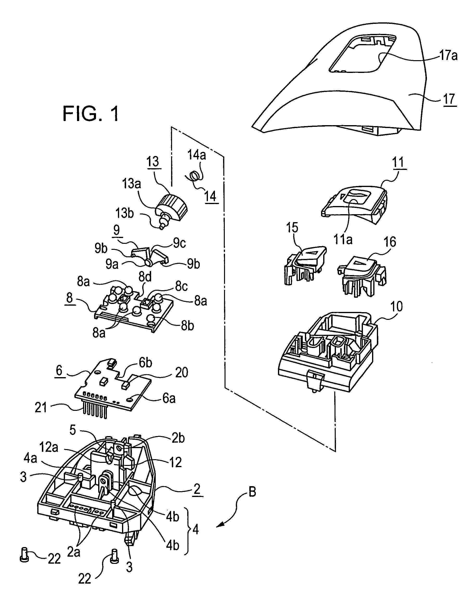
[0035]As shown in FIG. 2, the switch device 1 mainly includes a lower case 2 having, for example, positioning pins 3 and a tiltably-supporting portion 4 projected therefrom. A circuit board 6 is disposed inside the lower case 2 and has a wiring pattern that includes fixed contacts 7 on an upper surface of the circuit board 6. A rubber sheet 8 is disposed on the circuit board 6 and has a plurality of dome-shaped protuberances 8a. An actuator 9 has a tilting shaft 9a tiltably supported by the tiltably-supporting portion 4 and ends 9b dis...


PUM


Abstract

A switch device is provided. A switch device includes a housing. A circuit board is provided with fixed contacts. A rubber sheet is disposed on the circuit board and has protuberances, a tiltably-supported actuator, a rotatable knob, and a torsional coil spring serving as a restoring spring. The actuator is disposed adjacent to the rotatable knob. The rotatable knob is provided with a drive portion, which extends through a cutout in the actuator so as to be slidably engaged to engagement portions of the actuator.

Description

[0001]This application claims the benefit of Japanese Patent Application No. 2005-256917 filed on Sep. 5, 2005, Application No. 2005-256919 filed on Sep. 5, 2005 and Japanese Patent Application No. 2005-256920 filed on Sep. 5, 2005 which are both hereby incorporated by reference.BACKGROUND[0002]1. Field[0003]The present embodiments relate to a switch device.[0004]2. Related Art[0005]A typical example of a switch device of this type is disclosed in Japanese Unexamined Patent Application Publication No. 8-7701 (pages 3 to 4, FIG. 1). Such a switch device includes a pair of switch units disposed on a circuit board inside a housing. An actuator is disposed over the two switch units. A tiltable operating member is disposed on the actuator. In this conventional switch device, the operating member tiltably supported within the housing is partly exposed through a window of the housing so that a portion of the operating member can be manually operated by an operator. When the operating membe...

Claims


Application Information

Patent Timeline
Patent Type & Authority Patents(United States)
IPC IPC(8): H01H9/00
CPCH01H23/16H01H23/30H01H3/42H01H23/148H01H2221/018
Inventor HYUN, CHOI NOKSHIRAKAWA, MIKIOYOKOYAMA, TATSUYA
Owner ALPS ALPINE CO LTD
Why Eureka
Try Eureka