Method and system for producing dynamically determined drop shadows in a three-dimensional graphical user interface

a three-dimensional graphical user interface and drop shadow technology, applied in the field of data processing system, can solve the problems of overloading the cognitive capacity of the user, the inability of most users to feel that the interface is useful, and the computational cost of interface generation

Inactive Publication Date: 2008-10-21
ACTIVISION PUBLISHING
View PDF28 Cites 157 Cited by
  • Summary
  • Abstract
  • Description
  • Claims
  • Application Information

AI Technical Summary

Benefits of technology

[0017]A method, a system, an apparatus, and a computer program product are presented for generating a shadow effect for objects in a graphical user interface. The graphical user interface simulates a three-dimensional coordinate space by displaying objects whose dimensions are computed in the three-dimensional coordinate space. A shadow object corresponding to a first object is generated, and a determination is made for an occluding region of the shadow object that partially occludes an illumination of a second object. A z-dimensional differenc

Problems solved by technology

Hence, the amount of information that may be displayed on a computer screen at any given time has continued to increase, which could potentially overload a user cognitively.
While these types of graphical user interfaces may be slightly more spatially intuitive for a user, any information must still be presented using some form of metaphor, and the computer skills of most users are not sophisticated enough to feel that these interfaces are useful.
Moreover, these interfaces are computationally expensive to generate, thereby requiring computation resources that far exceed the computational resources of the common tasks of most users.
If the contents of a selected graphical object are enlarged or reduced in real-time during the opera

Method used


Image

  • Method and system for producing dynamically determined drop shadows in a three-dimensional graphical user interface
  • Method and system for producing dynamically determined drop shadows in a three-dimensional graphical user interface
  • Method and system for producing dynamically determined drop shadows in a three-dimensional graphical user interface

Examples


Embodiment Construction

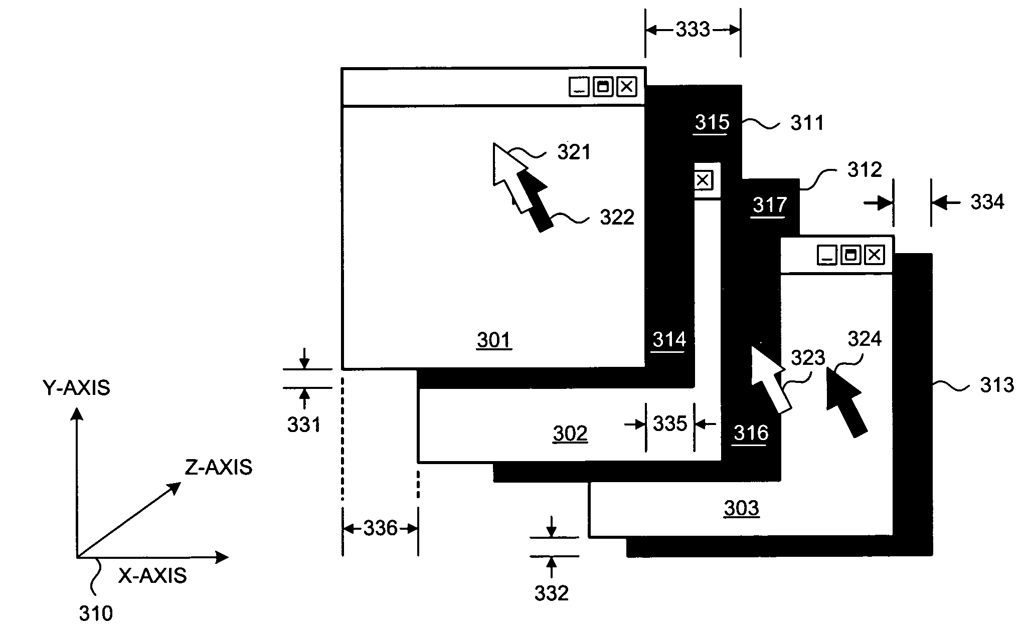
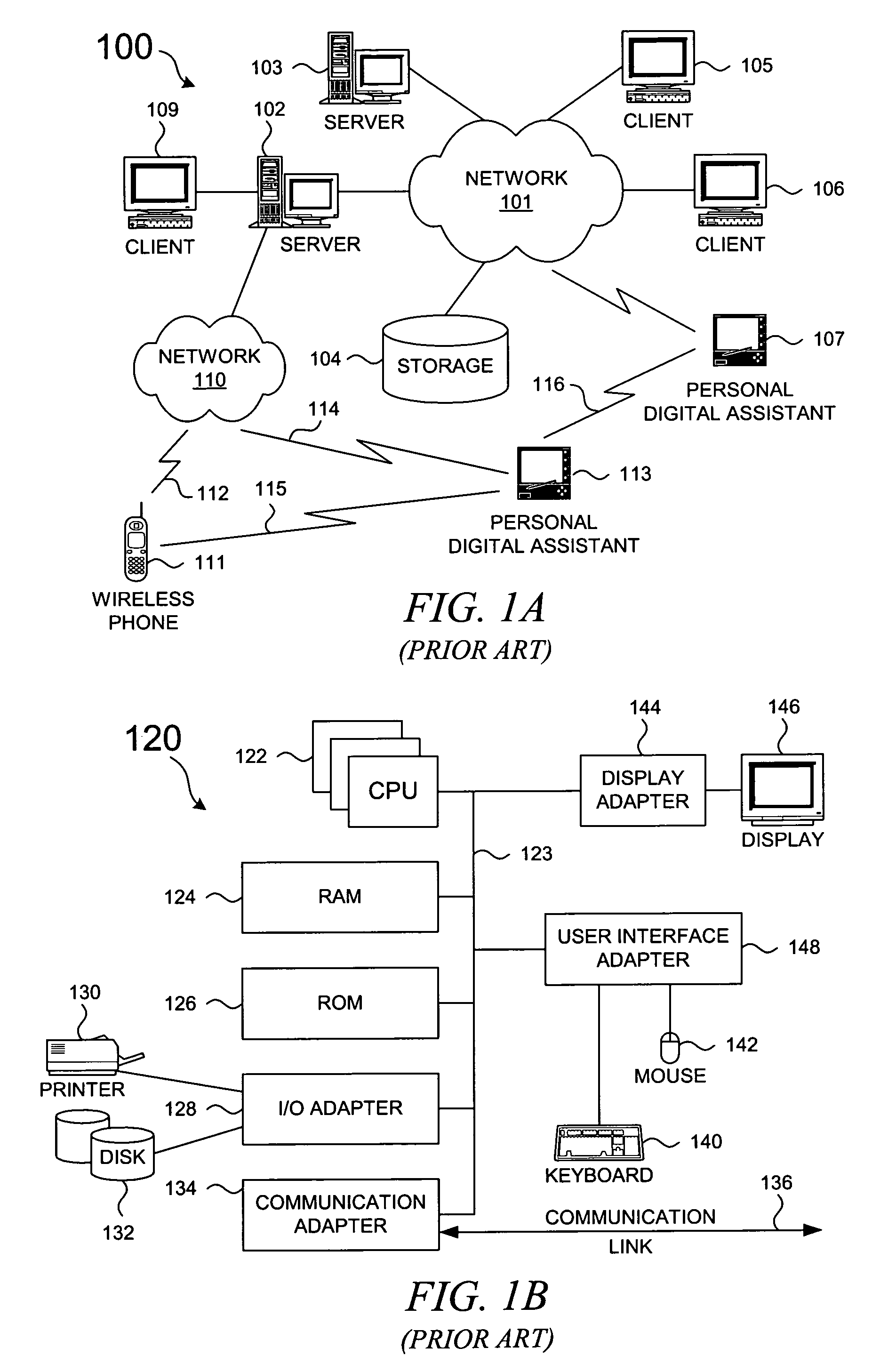
[0027]The present invention is directed to a visual effect that is associated with graphical objects that are presented within a graphical user interface on a computer display device. It should be noted that a dynamically determined drop shadow that is generated in accordance with the present invention can be generated on a computer device and presented on a display device that is connected to the generating computer device. In other cases, however, the dynamically determined drop shadow of the present invention can be generated in conjunction with other graphical data on a first computer device and then sent to a second computer device that subsequently displays the graphical data. Therefore, as background, a typical organization of hardware and software components within a distributed data processing system is described prior to describing the present invention in more detail.

[0028]With reference now to the figures, FIG. 1A depicts a typical network of data processing systems, eac...


PUM


Abstract

A methodology for generating a drop shadow effect for objects in a graphical user interface is presented. A first object in a presentation space occludes the illumination from a simulated light source, and a dynamically determined drop shadow from the first object may partially occlude a second object. A portion of a drop shadow from the first object is shown on the second object; the portion of the drop shadow from the first object is displaced from the first object in direct proportion to a z-depth difference between the first object and the second object. Hence, a drop shadow can be generated in a computationally inexpensive manner, and the dynamically determined drop shadow enhances the perception of depth within the presentation space by a user.

Description

BACKGROUND OF THE INVENTION[0001]1. Field of the Invention[0002]The present invention relates to an improved data processing system and, in particular, to a method and system for displaying graphical objects. Still more particularly, the present invention provides a method and system for rendering graphical objects in a three-dimensional operator interface or graphical user interface (GUI) environment.[0003]2. Description of Related Art[0004]A windowing metaphor is commonly used in graphical user interfaces of modern computer systems. The use of windows allows multiple application programs to simultaneously represent more than one set of display data on a single computer monitor. A graphical user interface typically allocates at least one display window on the computer screen for each executing application program.[0005]Most windowing systems manage the limited resource of screen space by manipulating a so-called two-and-one-half (2½D) dimensional presentation space in which the pre...

Claims


Application Information

Patent Timeline
IPC IPC(8): G06T15/50G06T15/60
CPCG06T15/60
Inventor HSU, JIMMY MING-DER
Owner ACTIVISION PUBLISHING
Why Eureka
Try Eureka