Ecological driving system

a driving system and environmental technology, applied in the field of environmental driving systems, can solve the problems of not being able to easily notify whether or not the user is responsible for idling, user may not be able to easily prevent an idling state, and not being able to fully conscious of environmental driving

Inactive Publication Date: 2008-10-21
DENSO CORP
View PDF11 Cites 32 Cited by
  • Summary
  • Abstract
  • Description
  • Claims
  • Application Information

AI Technical Summary

Benefits of technology

[0006]The present invention has been made in consideration of the foregoing. It is therefore an object of the present invention to provide an ecological driving system that allows a user to be conscious of environmentally friendly driving.

Problems solved by technology

For instance, the system notifies the user of such information that the engine is idling too long.
When the system only determines whether or not the engine is idling, the user can be simply notified of this information but cannot be easily notified whether or not the user is responsible for the idling state.
For example, the user may not be able to easily prevent an idling state, for which the user is not directly responsible, when the engine is idling because his or her vehicle waits for the traffic light to change at an intersection or temporarily stops due to traffic congestion.
Accordingly, the above system does not allow the user to be fully conscious of environmentally friendly driving.

Method used


Image

  • Ecological driving system
  • Ecological driving system
  • Ecological driving system

Examples


first embodiment

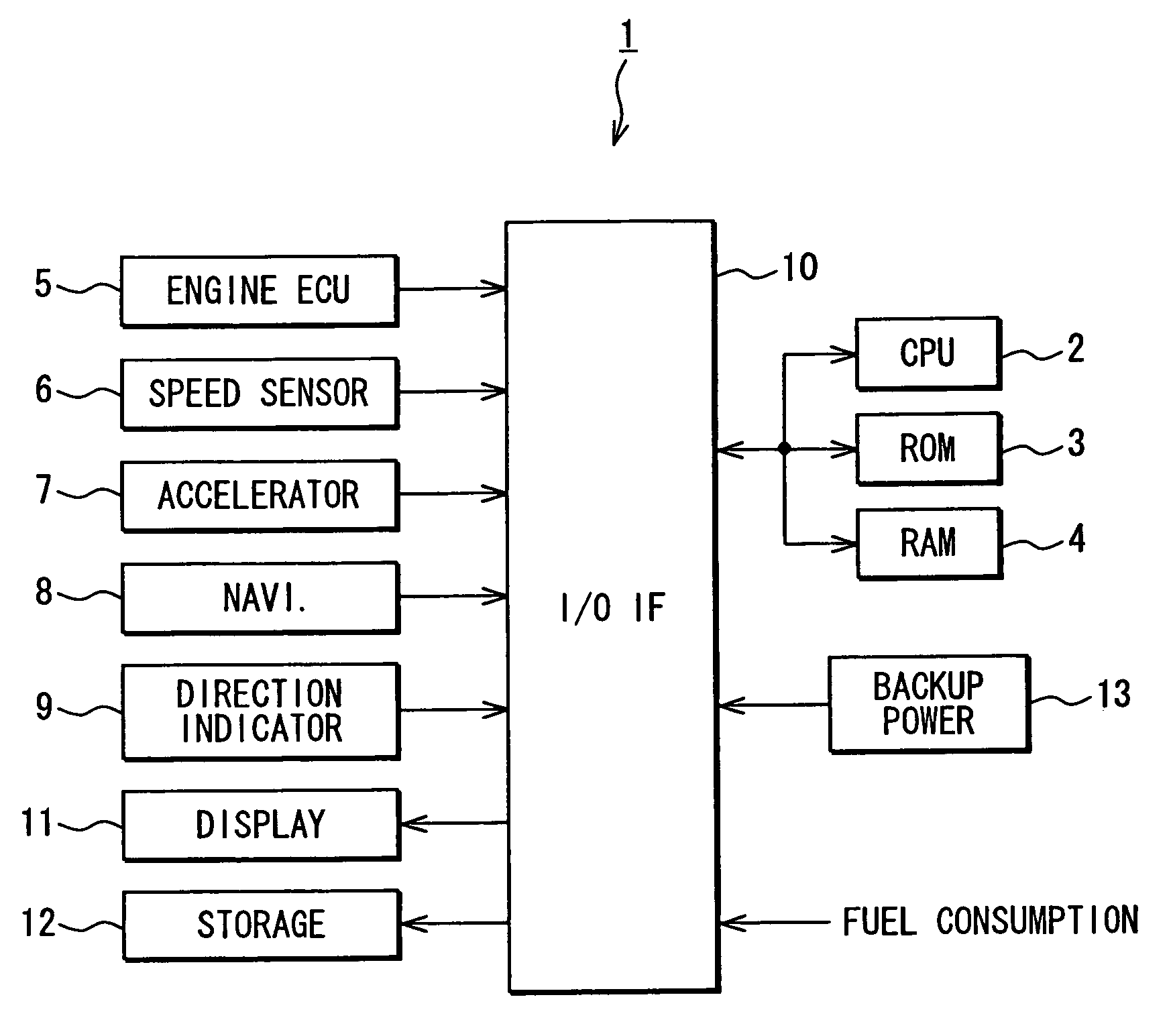
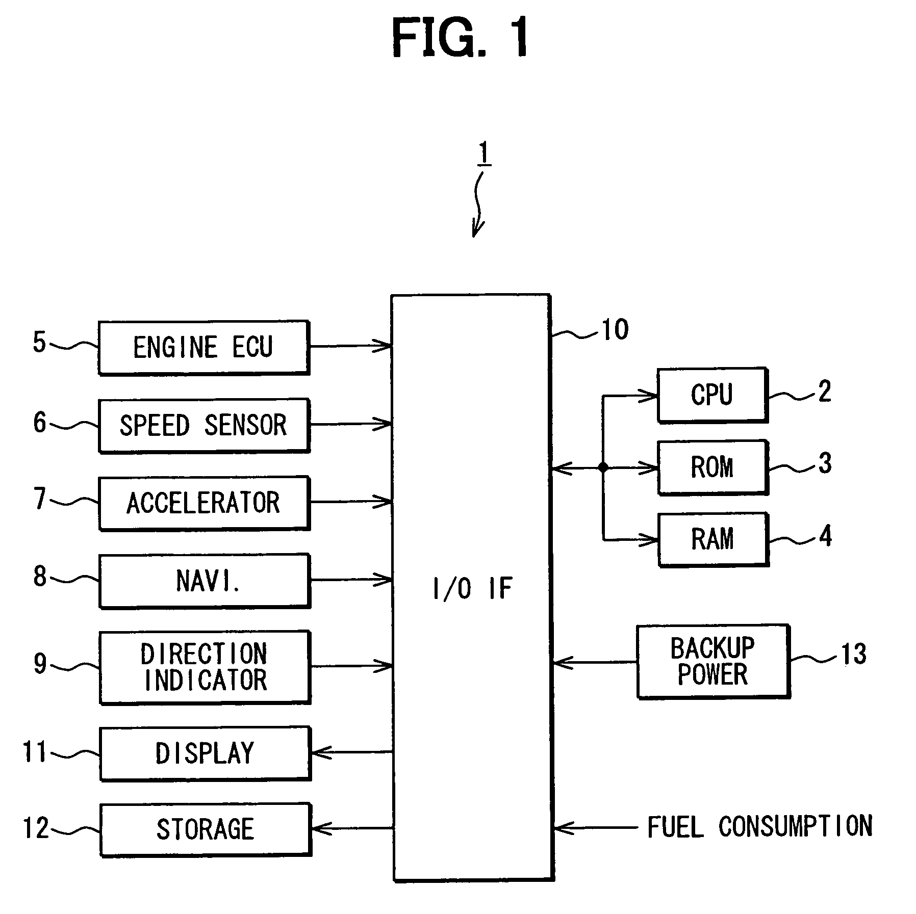
[0021]With reference to FIGS. 1 through 4, the following describes a first embodiment of the present invention applied to a vehicle that uses, as a single driving source, liquid fuel such as gasoline. FIG. 1 is a functional block diagram showing an overall construction of an ecological driving system 1 provided in the vehicle. In the ecological driving system 1, a CPU 2 (functioning as control means) reads and executes a control program stored in a ROM 3. In addition, the CPU 2 uses a RAM 4 as a work storage to control overall operations of the ecological driving system 1.

[0022]An engine ECU (Electronic Control Unit) 5 outputs an engine state signal indicating whether an engine is operating, stops, or warms up to increase the engine temperature. A vehicle speed sensor 6 outputs a vehicle speed signal indicating the vehicle speed. An accelerator 7 outputs an accelerator opening signal indicating the accelerator opening. A navigation apparatus 8 functioning as navigating means outputs...

second embodiment

[0039]With reference to FIGS. 5 through 10, the following describes a second embodiment of the invention. A description about the same part as the first embodiment is omitted and differences are described. The second embodiment is applied to a so-called hybrid vehicle that uses the liquid fuel and the electric power as a driving source. In an ecological driving system 21, a CPU 22 is supplied with the liquid fuel consumption from the outside via an input / output interface 23. In addition, the CPU 22 is supplied with the amount of battery charge and discharge via the input / output interface 23.

[0040]There are two methods of calculating the amount of battery charge and discharge. One is to measure the transition of output voltages from the battery. The other is to measure a difference between input power to the battery per unit time and output power from the battery per unit time.

[0041]FIG. 6 shows the method of measuring the transition of output voltages from the battery. This method p...


PUM


Abstract

There is a need for making a user fully conscious about environmentally friendly driving. In an ecological driving system, a CPU allows a display apparatus to distinctively display fuel consumption according to the following idling states. One idling state results from engine warm-up. Another is useless idling state. Still another idling state results when a vehicle waits for turning to the left at an intersection or stops at a roadside. Yet another idling state results when the vehicle waits for turning to the right at an intersection. Still yet another idling state results when the vehicle waits forward at an intersection or stops due to traffic congestion.

Description

CROSS REFERENCE TO RELATED APPLICATION[0001]This application is based on and incorporates herein by reference Japanese Patent Applications No. 2005-280249 filed on Sep. 27, 2005, and No. 2006-104136 filed on Apr. 5, 2006.FIELD OF THE INVENTION[0002]The invention relates to an ecological driving system that prompts a user to do environmentally friendly driving.BACKGROUND OF THE INVENTION[0003]For prompting a user to practice environmentally friendly driving, an example system evaluates user's driving situations and notifies the user of an evaluation result (e.g., see patent document 1).[0004]Patent document: JP-2002-104023A (US2002 / 0062191 A1)[0005]This type of system for prompting the user to do environmentally friendly driving determines simply whether or not an engine is idle. For instance, the system notifies the user of such information that the engine is idling too long. When the system only determines whether or not the engine is idling, the user can be simply notified of this...

Claims


Application Information

Patent Timeline
Patent Type & Authority Patents(United States)
IPC IPC(8): G06F19/00G06G7/70B60R16/02F02D29/02
CPCB60K6/48B60W30/18054B60W2550/402Y02T10/52Y02T10/56Y02T10/6221B60W2556/50Y02T10/40Y02T10/62Y02T10/84
Inventor TSUKAMOTO, AKIRATAUCHI, NOBUTAKA
Owner DENSO CORP
Why Eureka
Try Eureka