Ladder lock

Inactive Publication Date: 2008-11-04
SIZEMORE DANIEL
View PDF15 Cites 23 Cited by
  • Summary
  • Abstract
  • Description
  • Claims
  • Application Information

AI Technical Summary

Benefits of technology

[0012]For ease of transport, a clip on one rung of the ladder whereby a portio

Problems solved by technology

If the ladder slips on the surface below, the individual on the ladder may fall.
This is particularly true of the ladder surfaces placed on a tile or wood floor, which tend to be more slippery than traditional carpet or other surfaces, although the ladder can

Method used


Image

  • Ladder lock
  • Ladder lock
  • Ladder lock

Examples


Embodiment Construction

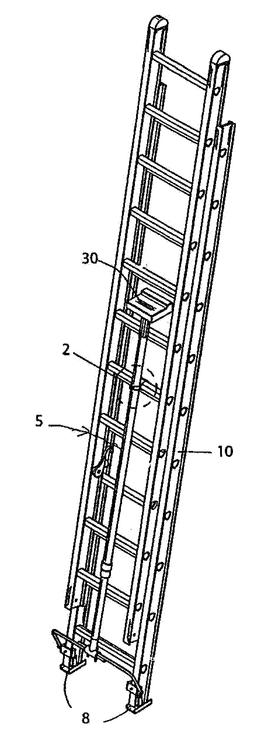
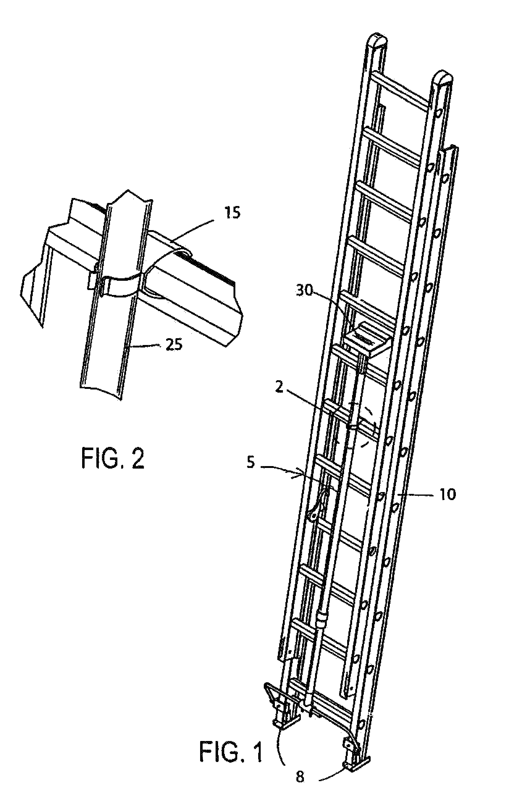
[0036]This device 5 is a safety device to be used with an extension ladder 10. The extension ladder has two pieces, one section rests on the floor and has a series of foot supports 8 and remains stationary. These foot supports 8 will rest on the ground surface during normal use. The other section will move parallel to the stationary member of the extension ladder.

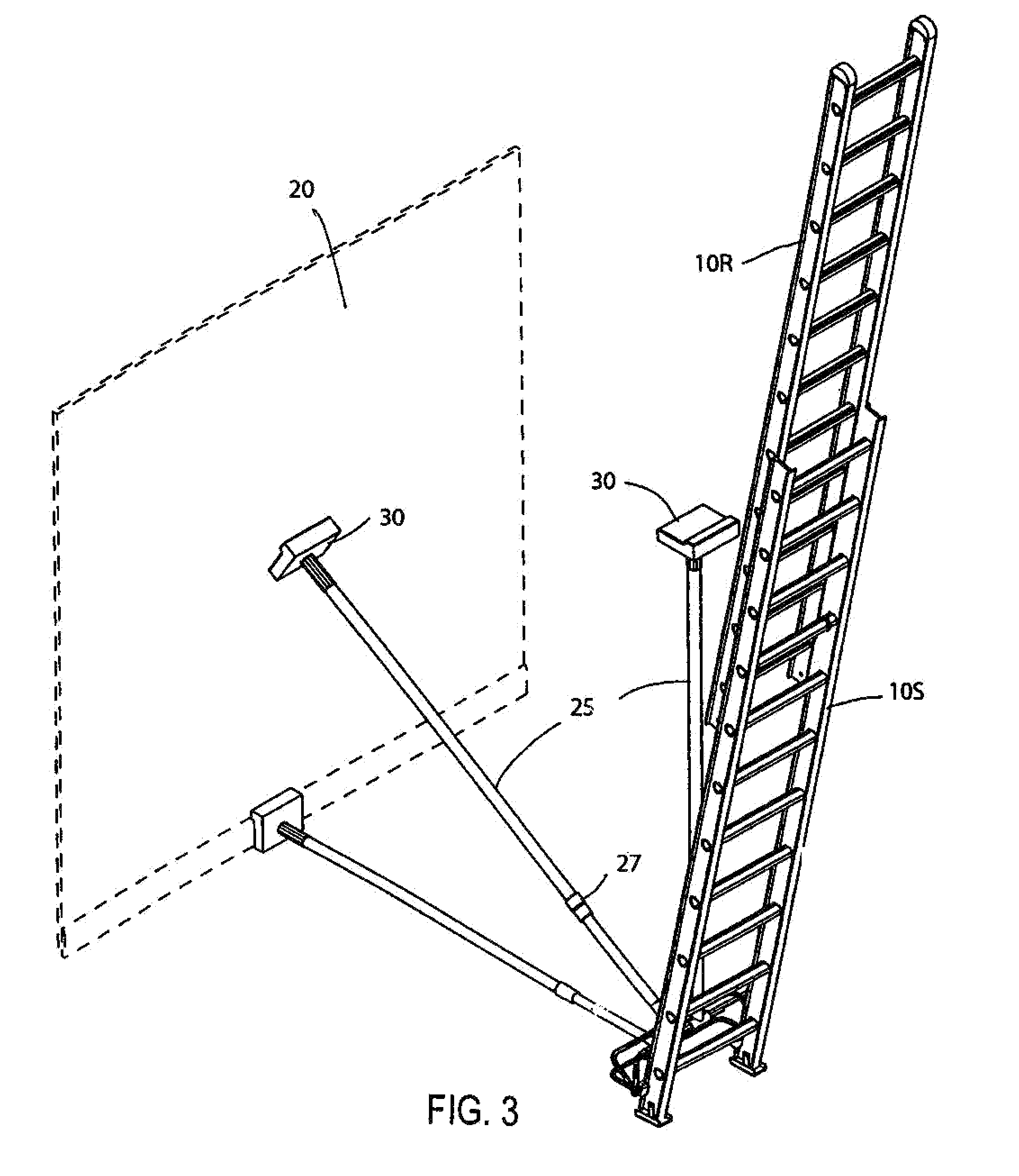
[0037]When the ladder is initially being positioned one section of the ladder will move up and down while the other section stays stationary. One section 10R will go up and down relative to the stationary portion 10S. This device will be clamped to the bottom of section 10S slightly above the foot supports 8 and below the first ladder rung. It is secured to the ladder member with a clamping mechanism 45, which take the general shape of a “U”. Various types of clamps may be used and the means to secure the clamping mechanism 45 to the extension ladder may include bolts as well as eye screws.

[0038]Two solid support structure ...


PUM


Abstract

This is a device that will provide additional security for individuals who work on extension ladders. It can be fit to any extension ladder and provide a support mechanism so that, if the ladder were ever to shift backward, it would stop the ladder from shifting, thereby protecting the worker. Because of the telescoping nature of the tube, it provides protection and it may be used in a variety of settings.

Description

BACKGROUND OF THE INVENTION[0001]A. Field of the Invention[0002]This relates to the use of an extension ladder and specifically the safe use of the extension ladder. This is an attachment piece that is attached near the bottom front of the ladder and will safely secure the extension ladder to a structure.[0003]B. Prior Art[0004]There are many other prior art references to ladder devices and specifically ladder devices, which seek to minimize injury as a result of a fall from a ladder. Representative examples of them are many in the prior art, and some attach to the structure and some to buildings. These types of structures can be found in the following representative patents: Bee, et al., U.S. Pat. No. 6,012,545, Boring, U.S. Pat. No. 4,974,669, Gardner, U.S. Pat. No. 5,960,905, and Griffin, U.S. Pat. No. 4,858,725.[0005]None of the prior art references, however, use a device that attaches to the ladder and is then secured by the frame of a structure as contemplated in this device.B...

Claims


Application Information

Patent Timeline
IPC IPC(8): E06C7/42
CPCE06C7/081E06C7/423
Inventor SIZEMORE, DANIEL
Owner SIZEMORE DANIEL
Why Eureka
Try Eureka