
Image heating apparatus with adjusted feeding force to sheet with toner image

a heating apparatus and toner image technology, applied in the field of image heating apparatus, can solve the problems of difficult separation of recording medium from fixation roller, unsatisfactory fixation image on recording medium, and lower recording medium releasing performance of lengthwise center portion of fixation nip

Inactive Publication Date: 2008-11-04
CANON KK
View PDF7 Cites 19 Cited by
  • Summary
  • Abstract
  • Description
  • Claims
  • Application Information

AI Technical Summary

Benefits of technology

The present invention is about an image heating apparatus that prevents wrinkling in recording medium. The technical effect of this invention is to improve the quality of printing and reduce the likelihood of defects in the finished product.

Problems solved by technology

However, a fixing apparatus of the belt-nip type structured in accordance with the prior art is technically problematic in that it has a tendency to wrinkle recording medium, preventing thereby the unfixed image on the recording medium from being satisfactorily fixed to the recording medium.
On the other hand, the attempt to minimize the possibility that the recording medium will be wrinkled tends to make it difficult for the recording medium to separate from the fixation roller.
In the case of a fixing apparatus such as the above described one, the fixation nip of which is shaped so that its lengthwise center portion is narrower than the lengthwise end portions, there is such a problem that the lengthwise center portion of the fixation nip is lower in recording medium releasing performance than the lengthwise end portions.
However, the prior art described above has the following problem.
However, it is difficult to accomplish both the object of preventing a fixing apparatus from causing an image from deviating in position, and the object of preventing a fixing apparatus from causing recording medium to wrinkle, by adjusting only the ratio between the pressures P1 and P2.
Thus, it is possible that as the fixing operation continues, the fixing apparatus will begin to cause the recording medium to develop wrinkles while it conveys the recording medium through it.
On the other hand, if a fixing apparatus is designed so that P1 / P2 is very low in value at the beginning of the fixing operation, the apparatus tends to cause the positional image deviation, which is obvious, making it impossible to obtains a satisfactory image.
In the case of the structure disclosed in Japanese Laid-open Patent Application 2001-201979, it is difficult to improve a fixing apparatus in terms of recording medium release while preventing the pressure roller 103a of the fixing apparatus from causing the recording medium to develop wrinkles.
Therefore, reversely crowning the support roller 103b and steering roller 103c is not enough to completely solve the above described problem.

Method used


Image

  • Image heating apparatus with adjusted feeding force to sheet with toner image
  • Image heating apparatus with adjusted feeding force to sheet with toner image
  • Image heating apparatus with adjusted feeding force to sheet with toner image

Examples


embodiment 1

(Fixing Apparatus)

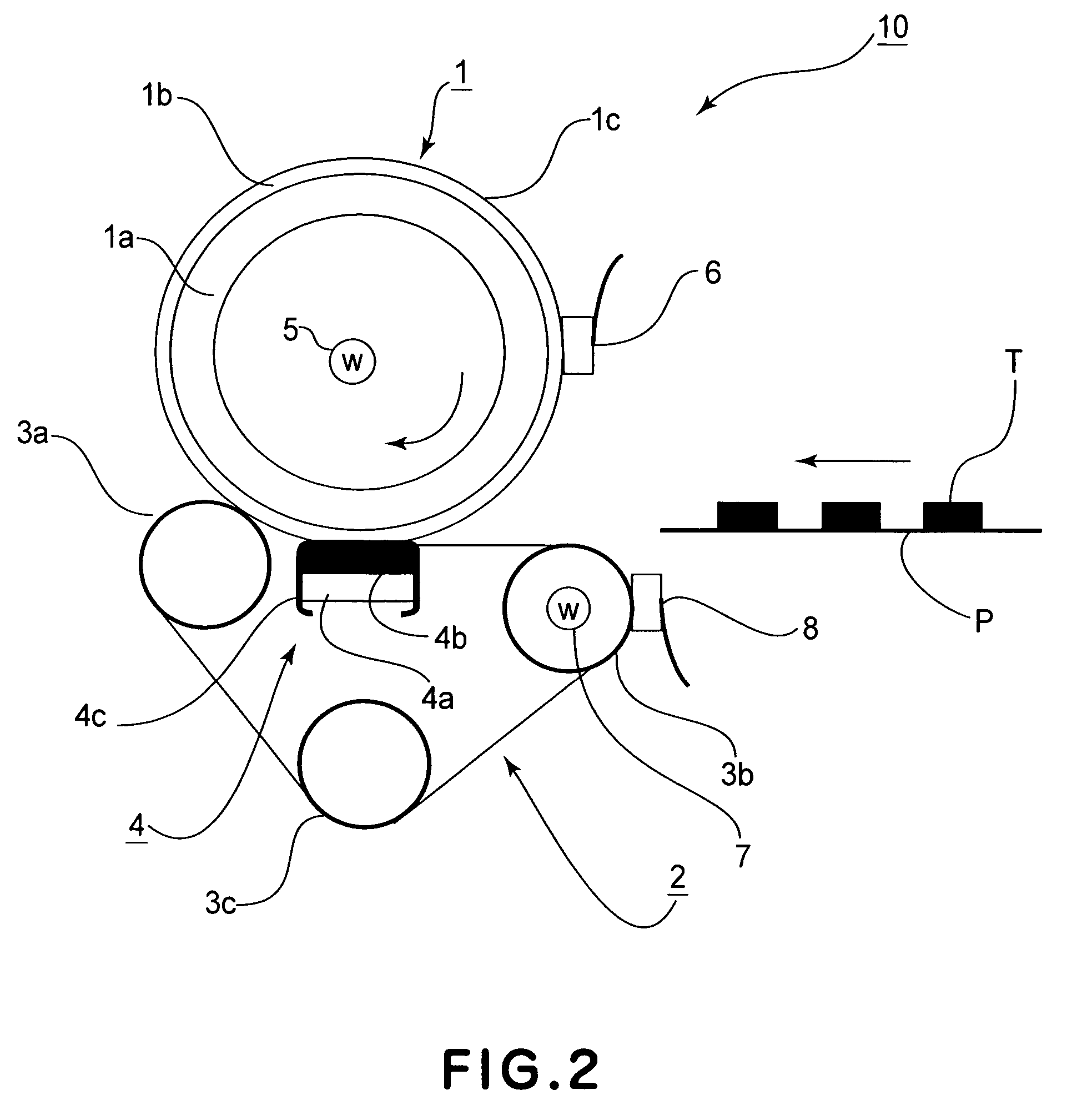
[0045]FIG. 2 is a schematic sectional view of an image heating apparatus as a fixing apparatus.

[0046]The fixing apparatus 10 in this embodiment is provided with a fixation roller 1, an endless belt 2, a pressure roller 3a, a heat roller 3b, a steering roller 3c, and a pressure pad 4.

[0047]As shown in FIG. 2, the fixation roller 1 is a rotatable heating member which contains a heat source. The fixation roller 1 is rotationally driven by an unshown driving force source in the direction indicated by an arrow mark at a preset peripheral velocity. The fixation roller 1 is provided with a metallic core 1a. As the metallic core 1a, a rod formed of aluminum, iron, or the like is employed. The peripheral surface of the metallic core 1a is coated with an elastic layer 1b formed of silicone rubber, and the outward surface of the elastic layer 1b is coated with a release layer 1c formed of fluorinated resin.

[0048]Within the hollow of the metallic core 1a, a halogen lamp 5 as t...


PUM


Abstract

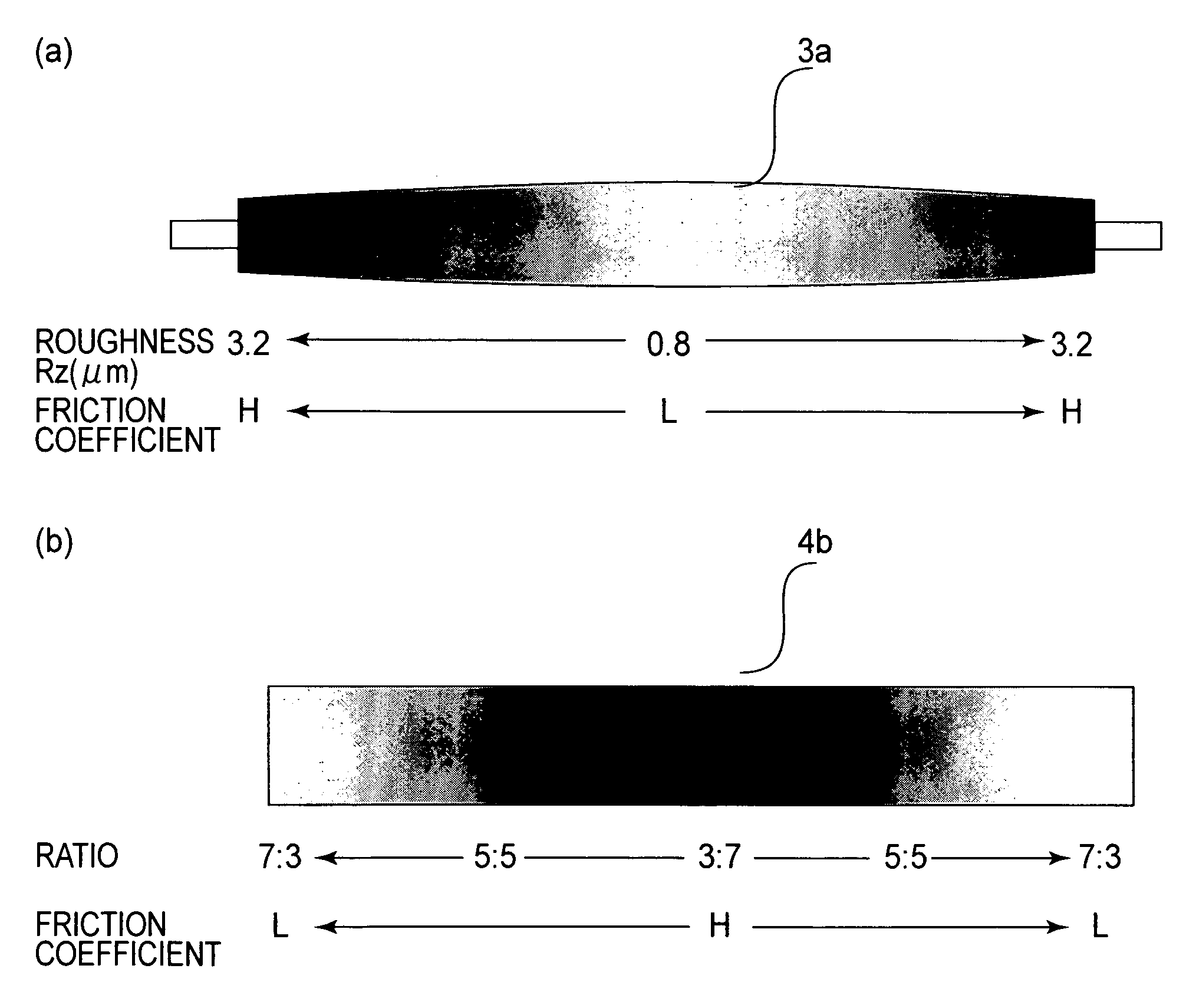
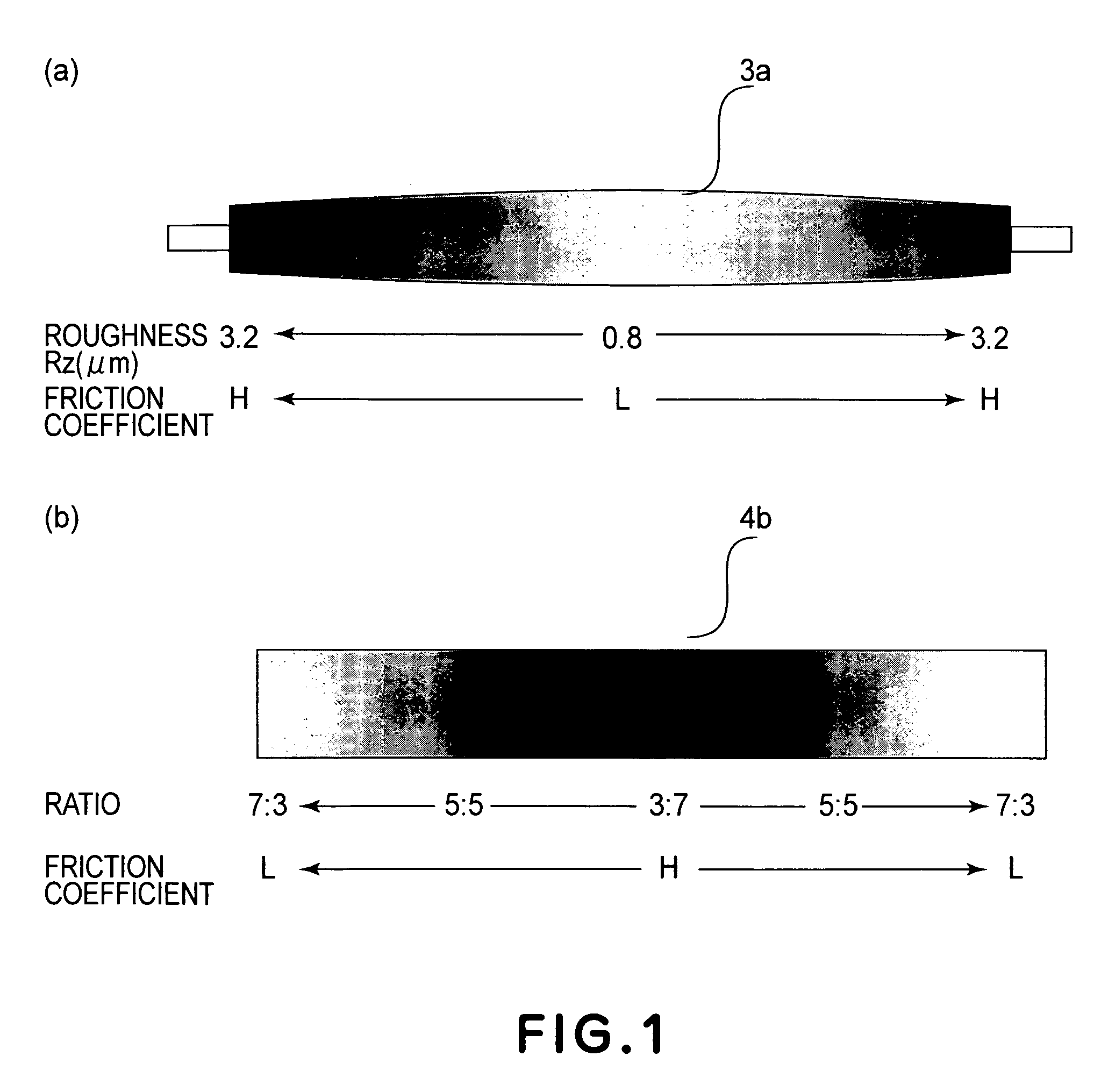
An image heating apparatus includes a heating rotatable member for forming a nip and heating an image on a recording material at the nip; an endless belt cooperative with the heating rotatable member to form the nip; and a pressing roller for pressing the belt toward the heating rotatable member at the nip, the roller having a diameter which is larger at an axially central portion thereof than at opposite end portions thereof and having a friction coefficient which is smaller at the axially central portion than at the opposite end portions.

Description

FIELD OF THE INVENTION AND RELATED ART[0001]The present invention relates to an image heating apparatus for heating an image on recording medium. Such an image heating apparatus is employed by a copying machine, a printing machine, a facsimile machine, etc.[0002]A fixing apparatus which thermally fixes an unfixed toner image has long been employed by an image forming apparatus such as a copying machine, a printing machine, a facsimile machine, etc., which employs an electrophotographic image forming method. As an example of such a fixing apparatus, there is a fixing apparatus of the belt-nip type, which is made up of a fixation roller having a heat source, a pressure roller, and a fixation belt. The fixation belt is kept pressed upon the fixation roller by the pressure roller.[0003]Japanese Laid-open Patent Application 10-228199 discloses a fixing apparatus of the belt-nip type. This fixing apparatus is made up of a fixation roller, an endless belt, and a pressure pad. The fixation ...

Claims


Application Information

Patent Timeline
Patent Type & Authority Patents(United States)
IPC IPC(8): G03G15/20
CPCG03G15/206G03G2215/2016G03G2215/2022G03G2215/2048G03G2215/2064
Inventor FUJINO, TAKESHI
Owner CANON KK
Learn More