

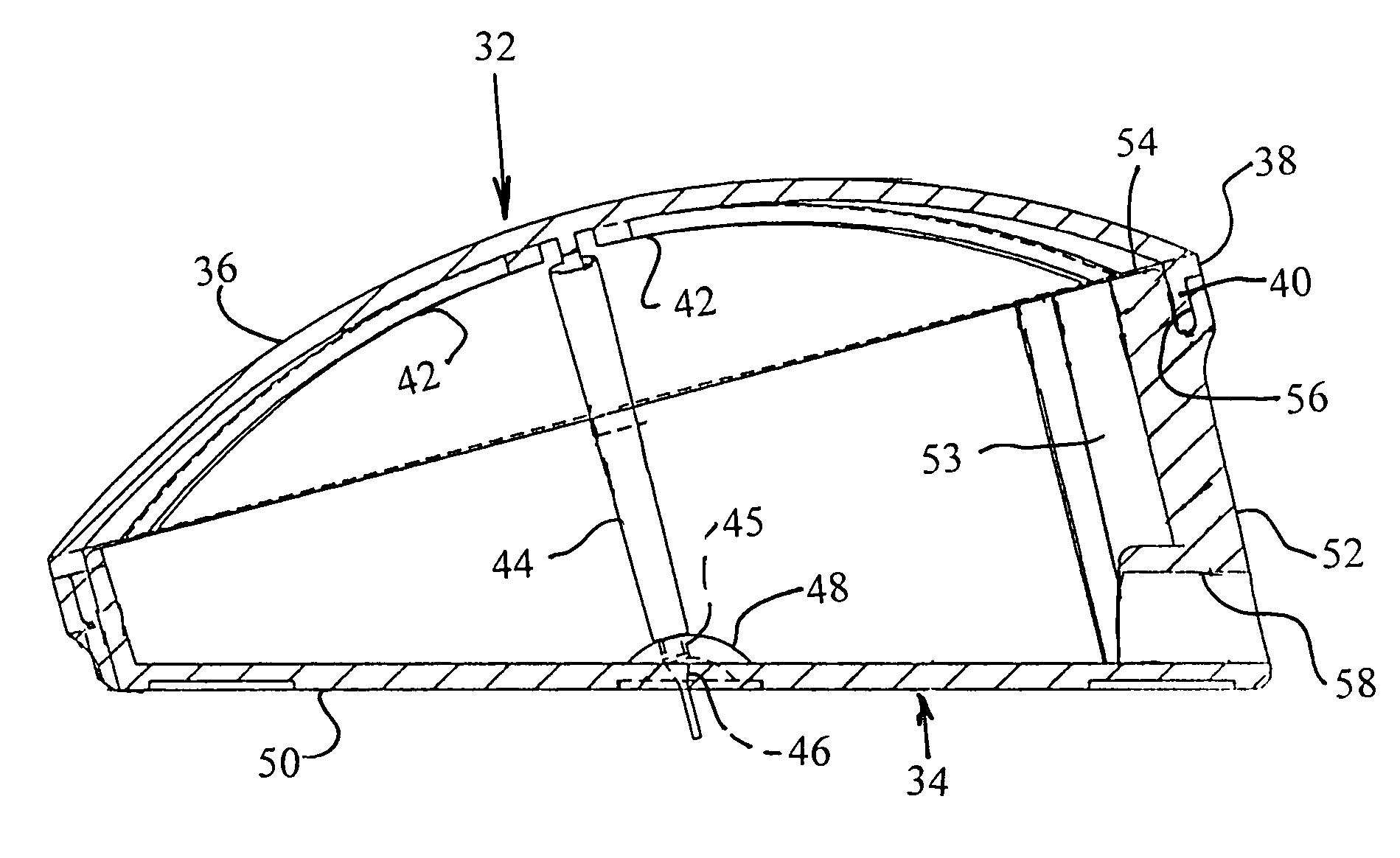
Elliptical pneumatic actuator with a wedge shaped base
a pneumatic actuator and elliptical technology, applied in vehicle tyre testing, roads, instruments, etc., can solve the fundamental instability of the bulb on a flat surface, the inability to be relied on to remain in a fixed or desired position on a patient's mattress, and the inability to control the inclination of the bulb
- Summary
- Abstract
- Description
- Claims
- Application Information
AI Technical Summary
Problems solved by technology
Method used
Image

Examples
Embodiment Construction
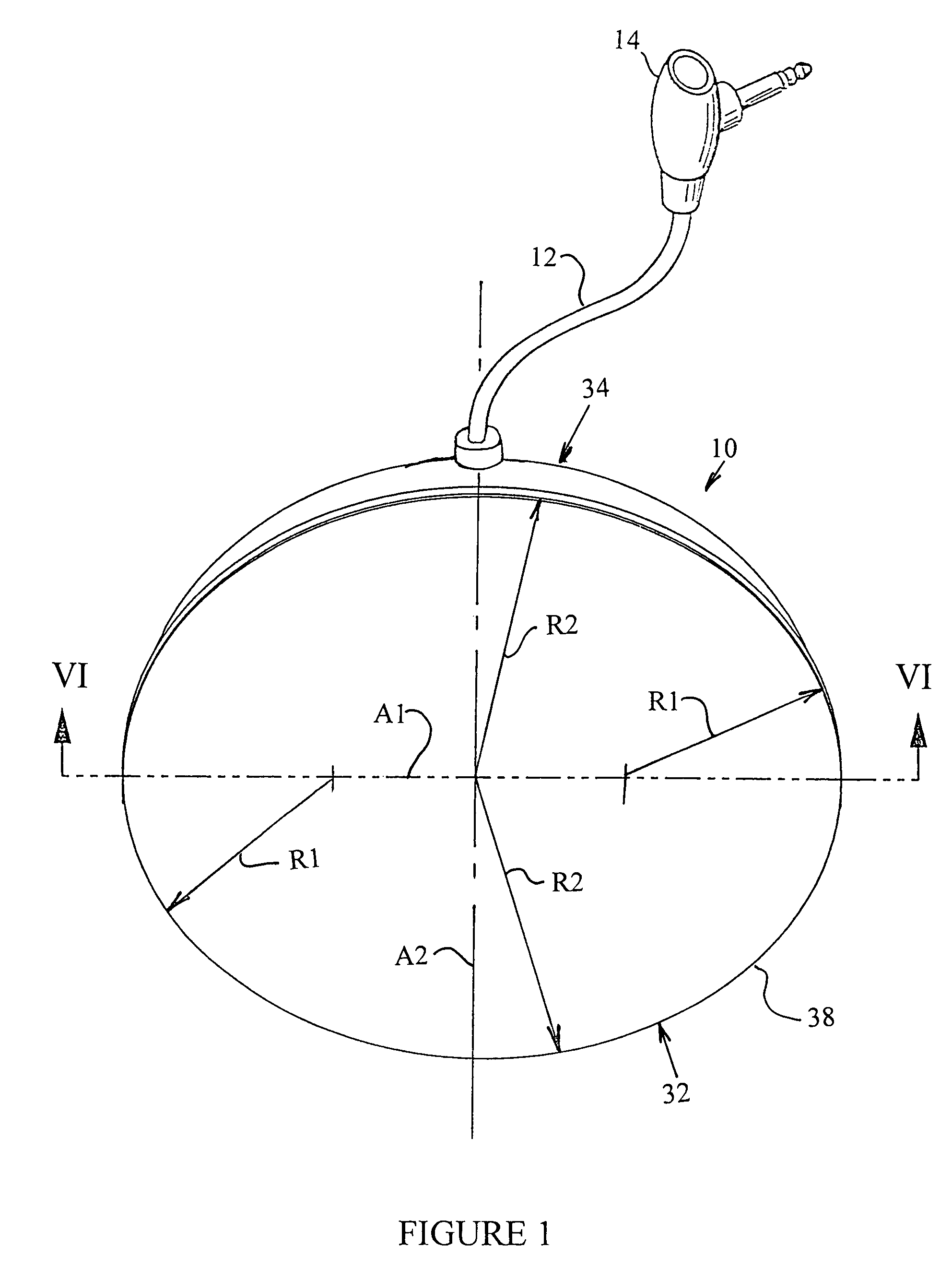
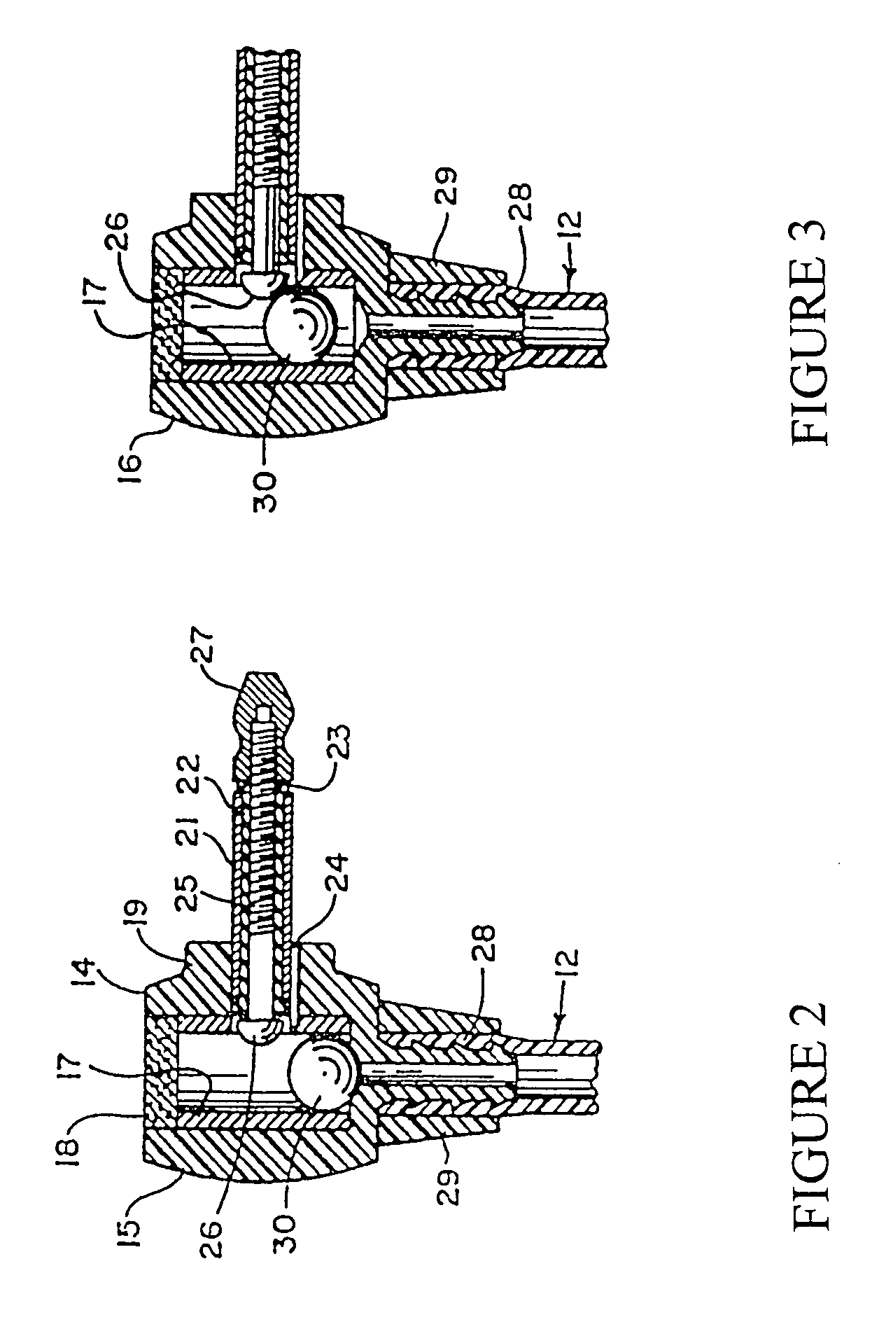
[0019]In FIG. 1 there is illustrated the preferred embodiment of the elliptical pneumatic actuator 10 according to the present invention. The elliptical pneumatic actuator 10 is connected in a manner per se well known in the art, by an air conduit 12 to a pneumatically actuated switching device 14 that is in turn connected electrically with a circuit, not shown, at some remote site for producing an alarm signal that is detected by personnel, such as a nurse. The present invention is particularly useful in a nurse call system utilized by patients to summon help for assistance or fulfill a need for patient care. The switch device 14 is shown in greater detail in FIGS. 2 and 3 and includes an actuator housing 16 having an internal annular cavity for supporting a sleeve 17. The sleeve 17 seats against a bottom wall of the cavity in the housing 16. The top of the cavity is enclosed by a porous air filter 18. Emerging through an opening surrounded by an enlarged boss 19 in a sidewall of t...
PUM
 Abstract
Description
Claims
Application Information