Tamper resistant assembly for an electrical receptacle

a technology of electrical receptacles and assembly parts, which is applied in the direction of coupling devices, two-part coupling devices, electrical apparatus, etc., can solve the problems of serious injury of children who insert paper clips or the conductive portion of toys into energized conductive elements,

Active Publication Date: 2008-11-18
HUBBELL INC
View PDF29 Cites 57 Cited by
  • Summary
  • Abstract
  • Description
  • Claims
  • Application Information

AI Technical Summary

Benefits of technology

[0009]A further objective of the present invention is to provide an improved tamper resistant assembly having a reduced number of parts.
[0011]The foregoing objectives are basically attained by a tamper resistant assembly including a base member having first and second grooves. Each groove has a first portion and a second portion connected to the first portion. The first portion is substantially perpendicular to a rear wall of the member and the second portion forms an obtuse angle with the first portion. A shutter member is slidably and pivotally connected to the base member for movement between open and closed positions. First and second protrusions extend outwardly from the shutter member and are slidably and pivotally received in the first and second grooves, respectively, in the base member. The first and second protrusions are disposed in the first portions of the grooves when the shutter member is in the closed position and prevent lateral sliding of the shutter member to prevent insertion of a foreign object past the shutter member and in the second portions when the shutter member is in the open position by allowing lateral sliding of the shutter member. The first portions prevent lateral movement of the shutter member and allow pivoting movement of the shutter member to positions preventing insertion of the foreign object past the shutter member.
[0012]The foregoing objectives are also basically attained by an electrical receptacle having a tamper resistant assembly disposed therein. The electrical receptacle includes a front cover and a back housing secured to the front cover. A tamper resistant assembly is disposed between the front cover and the back housing. A base member has first and second side walls extending forwardly from a rear wall. First and second grooves are formed in the first side wall of the base member and third and fourth grooves are formed in the second side wall. Each groove has a first portion and a second portion connected to the first portion. The first portion is substantially perpendicular to the rear wall of the base member and the second portion forms an obtuse angle with the first portion. A shutter member is slidably and pivotally connected to the base member for movement between open and closed positions. First and second protrusions extend outwardly from the shutter member and are slidably and pivotally received in the first and second grooves in the base member and third and fourth protrusions extend outwardly from the shutter member and are slidably and pivotally received in the third and fourth grooves. The protrusions are disposed in the first portions of the grooves when the shutter member is in the closed position and prevent lateral sliding of the shutter member to prevent insertion of a foreign object past the shutter member and in the second portions when the shutter member is in the open position by allowing lateral sliding of the shutter member. The first portions prevent lateral movement of the shutter member and allow pivoting movement of the shutter member to positions preventing insertion of the foreign object past the shutter member.

Problems solved by technology

A child inserting, for example, a paper clip or the conductive portion of a toy into the energized conductive elements can be seriously injured.
However, the Bowden '607 patent requires two shutter members to properly provide tamper resistance to the electrical receptacle.

Method used


Image

  • Tamper resistant assembly for an electrical receptacle
  • Tamper resistant assembly for an electrical receptacle
  • Tamper resistant assembly for an electrical receptacle

Examples


second exemplary embodiment

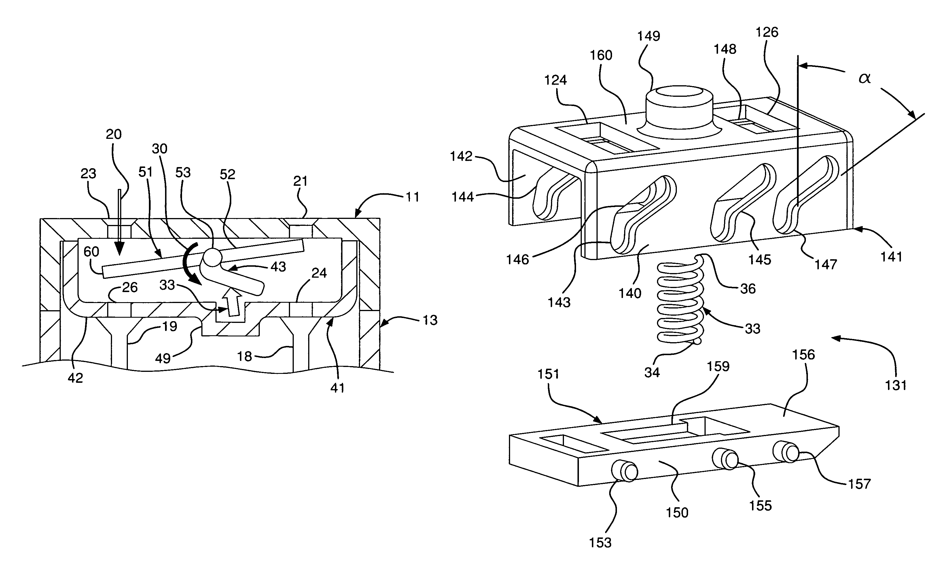
[0044]A second exemplary embodiment of the tamper resistant assembly is shown in FIGS. 8 and 9. The back housing 13, front cover 11, electrical contacts 18 and 19 and the spring 33 are substantially identical to those of the first exemplary embodiment described above.

[0045]The tamper resistant assembly 131 according to a second exemplary embodiment, as shown in FIGS. 8 and 9, includes a base member 141, a shutter member 151 and a spring 33. First, second and third grooves 143, 145 and 147 are formed in a first sidewall 140 of the base member 41, and fourth, fifth and sixth grooves 144, 146 and 148 are formed in a second sidewall 142 of the base member 141. A recess 149 in the rear wall 160 of the base member 141 receives the second end 36 of the spring 33. Each groove is substantially similar to the first and second grooves 43 and 44 described with regard to the first exemplary embodiment.

[0046]A shutter member 151 is slidably connected to the base member 141. First, second and thir...

third exemplary embodiment

[0048]A third exemplary embodiment of the tamper resistant assembly is shown in FIGS. 10-15. The back housing 13, front cover 11, electrical contacts 18 and 19 and the spring 33 are substantially identical to those of the first exemplary embodiment described above. The base member is substantially identical to the base member 141 of the second exemplary embodiment described above.

[0049]The tamper resistant assembly 231 according to a third exemplary embodiment, as shown in FIGS. 10-15, includes the base member 141 of the second exemplary embodiment, a shutter member 251 and a spring 33. The shutter member 251 is substantially similar to the shutter member 151 of the second exemplary embodiment with a second opening 263 in addition to the first opening 261.

[0050]Assembly and operation of the tamper resistant assembly 131 of the third exemplary embodiment shown in FIGS. 10-15 is substantially similar to that of the first exemplary embodiment described above and shown in FIGS. 1-7.

[005...


PUM


Abstract

A tamper resistant assembly provides tamper resistance to an electrical receptacle. The tamper resistant assembly includes a base member having first and second grooves. Each groove has a first portion and a second portion connected to the first portion. The first portion is substantially perpendicular to a rear wall of the member and the second portion forms an angle with the first portion. A shutter member is slidably and pivotally connected to the base member for movement between open and closed positions. First and second protrusions extend outwardly from the shutter member and are slidably and pivotally received in the first and second grooves, respectively, in the base member. The first and second protrusions are disposed in the first portions of the grooves when the shutter member is in the closed position and prevent lateral sliding movement of the shutter member to prevent insertion of a foreign object past the shutter member, and in the second portions when the shutter member is in the open position by allowing lateral sliding of the shutter member. The first portions prevent lateral movement of the shutter member and allow pivoting movement of the shutter member to positions preventing insertion of a foreign object past the shutter member.

Description

FIELD OF THE INVENTION[0001]The present invention relates to a tamper resistant assembly for an electrical receptacle. More particularly, the present invention relates to a tamper resistant electrical receptacle having a shutter member that is movable in two dimensions. Still more particularly, the present invention relates to a tamper resistant assembly for an electrical receptacle in which the base member of the tamper resistant assembly has a groove for receiving a protrusion of a shutter member to prevent accidental movement of the shutter member and in which a second portion of the groove is connected to and forms an angle with a first portion of the groove.BACKGROUND OF THE INVENTION[0002]A group of electrical receptacles is referred to as “protective” receptacles because some measure has been taken in the construction to protect children and others from harm if they should intentionally or inadvertently insert or attempt to insert an electrically conductive article into the e...

Claims


Application Information

Patent Timeline
Patent Type & Authority Patents(United States)
IPC IPC(8): H01R13/44
CPCH01R13/4534H01R24/78H01R13/4536H01R13/4538
Inventor ODDSEN, DENNIS A.MARCHETTI, MICHAEL J.
Owner HUBBELL INC
Why Eureka
Try Eureka