Miniature balanced antenna with differential feed

a technology of differential feed and antenna system, applied in the direction of antenna details, electrically short antennas, antennas, etc., can solve the problems of unbalanced antennas, unbalanced transmission lines, unbalanced antennas for transmitting and receiving radio frequency (rf) signals, etc., to reduce performance, reduce the need for complex impedance matching networks, the effect of minimizing the width of the antenna system

Active Publication Date: 2008-11-18
HONG KONG APPLIED SCI & TECH RES INST
View PDF16 Cites 5 Cited by
  • Summary
  • Abstract
  • Description
  • Claims
  • Application Information

AI Technical Summary

Benefits of technology

[0005]Various embodiments of the present invention include systems and methods for communication using balanced antenna systems. The following discussion describes one or more examples. In one embodiment, an antenna system includes two metallic portions separated by a capacitive gap, wherein the first portion is connected to differential inputs from a pair of transmission lines and designated as “fed element”, and the second portion is electromagnetically coupled by the fed element through the gap and acts as a “parasitic element”. The example antenna system, i.e. both fed and parasitic elements, is ungrounded and provides wideband performance. Further, the system is symmetrical in geometry. RF energy from the differential inputs excites and resonates the fed element, and in turn, the parasitic element by electromagnetic coupling. Both fed and parasitic elements interact mutually and resonate at their specific frequencies causing radiation of RF energy.
[0007]Between the fed element and the parasitic element is a dielectric gap that can be designed to provide impedance matching for the whole antenna system, possibly eliminating the need for a complex impedance matching network. Further, the balanced nature of this example antenna system dispenses with the need for a lossy balun that decreases performance in prior art systems.
[0008]While some embodiments use a straight parasitic element placed nearby the fed element, the footprint of this example embodiment can be made smaller by conforming the shape of the parasitic element to the shape of the fed element. In one example, the parasitic element “wraps around” the fed element, thereby surrounding at least part of the fed element and minimizing a width of the antenna system.

Problems solved by technology

Prior art systems, both consumer systems and commercial systems, typically employ unbalanced antennas for transmitting and receiving Radio Frequency (RF) signals.
Most unbalanced antennas have asymmetrical radiating portions and are fed by unbalanced transmission lines (e.g. coaxial cable or microstrip line) or sources.
There are several reasons why prior art systems employ unbalanced antennas.
Also, it is often true that for a particular design an unbalanced antenna is smaller in size than its corresponding balanced design.
Still further, there are four or five decades of unbalanced antenna engineering and research, such that most designers are more familiar or comfortable with unbalanced systems than with balanced systems.
In such applications, the balun receives an unbalanced input and transforms it into a balanced output, thereby matching the antenna element to the LNA, but with some amount of loss.
However, baluns adapted for use in wide band applications tend to cause loss that may be unacceptable for some devices.
Moreover, baluns with wide band characteristic are usually complex and tend to increase design and manufacturing costs.
By contrast, prior art balanced antenna systems tend to be large, and thus, are generally limited to applications wherein minimal loss is more important than space.
Further, balanced antenna systems often employ complex impedance matching circuits that are expensive and / or hard to design.

Method used


Image

  • Miniature balanced antenna with differential feed
  • Miniature balanced antenna with differential feed
  • Miniature balanced antenna with differential feed

Examples


Embodiment Construction

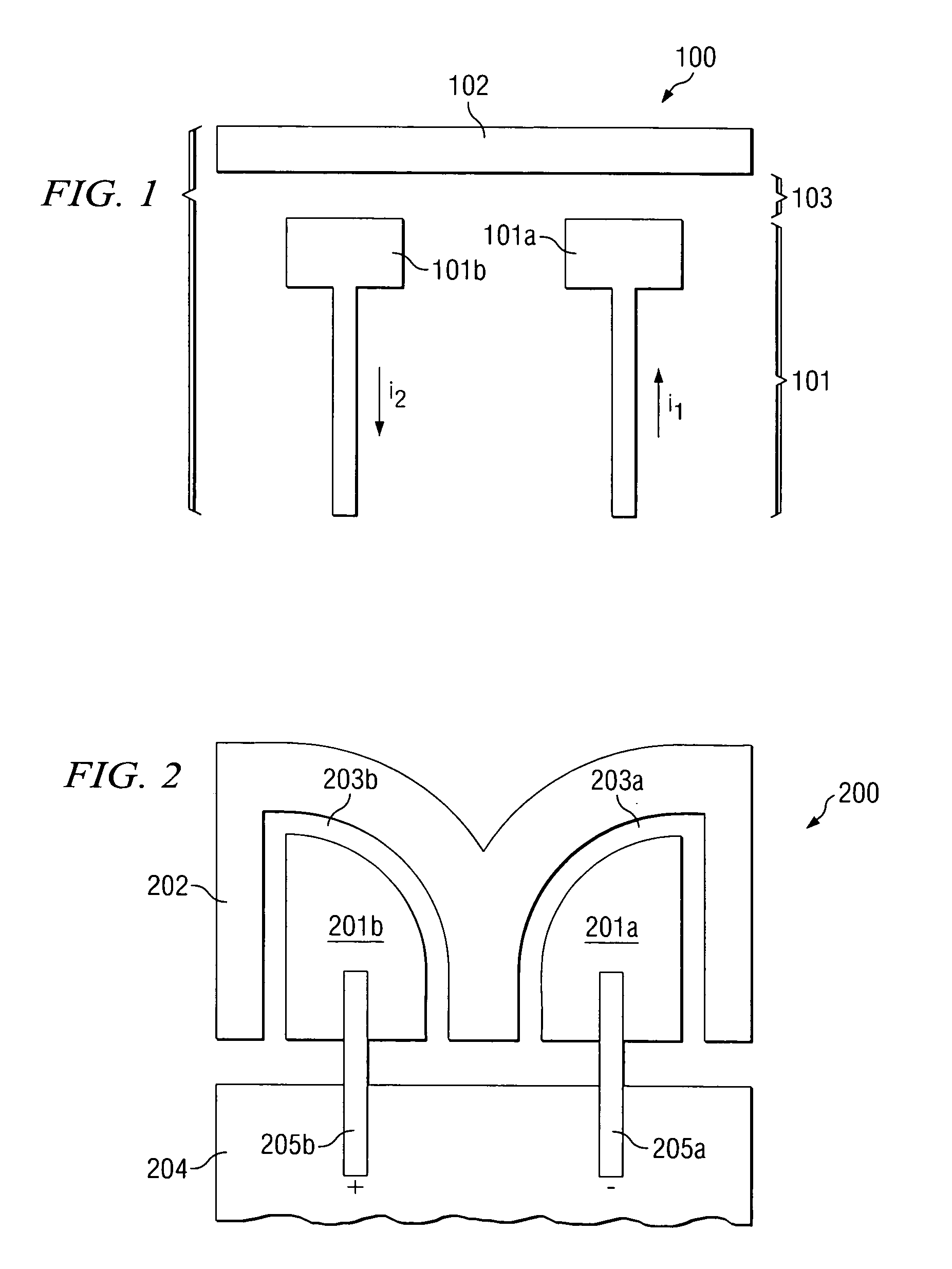
[0020]FIG. 1 is an illustration of exemplary antenna system 100 adapted according to one embodiment of the invention, System 100 includes metallic fed element 101 and metallic parasitic element 102. Individual fed element 101a and 101b are “balanced” in that their currents (or potentials) are equal in magnitude and completely out of phase along their respective paths. Accordingly, it is also true that fed element 101 is a differential structure, with one side acting as a “+” side and the other side acting as a “−” side. Gap 103 is a dielectric gap and may include air, plastic, fiberglass, or other dielectric materials.

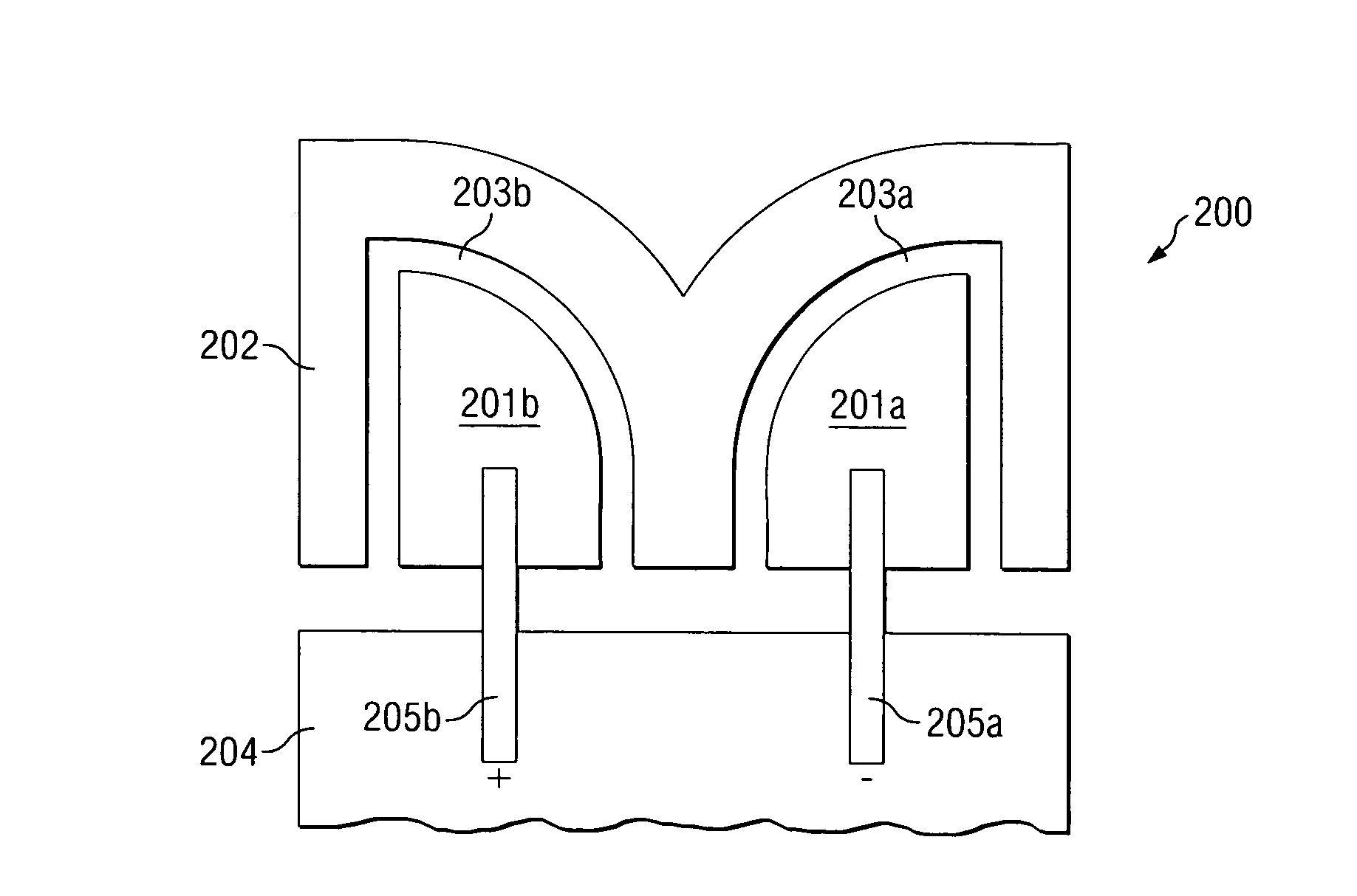
[0021]Metallic element 102 is a parasitic element that is symmetrical with respect to the polarity of fed element 101 and is separated therefrom by gap 103. Parasitic element 102 has one or more resonating frequencies, and when RF signals are provided to fed element 101 at a resonating frequency, parasitic element 102 resonates due to capacitive coupling. Fed element 1...


PUM


Abstract

An example antenna system includes a parasitic element and a symmetrical element fed by a balanced RF signal source. The fed element is operable to couple with the parasitic element, thereby causing the parasitic element to resonate at a first frequency band. Thus, the fed element is operable to act as a balanced capacitive feed for the parasitic element. Also, the parasitic element is symmetrical with respect to a polarity of the fed element.

Description

TECHNICAL FIELD[0001]The present invention relates in general to antenna systems and, more specifically, to balanced antenna systems with differential feeds. The invention further relates to miniaturized antenna systems with wide bandwidth operations.BACKGROUND OF THE INVENTION[0002]Prior art systems, both consumer systems and commercial systems, typically employ unbalanced antennas for transmitting and receiving Radio Frequency (RF) signals. Most unbalanced antennas have asymmetrical radiating portions and are fed by unbalanced transmission lines (e.g. coaxial cable or microstrip line) or sources. An example of an unbalanced antenna is a common monopole antenna system that has a single antenna element (a vertical straight metallic post with quarter freespace wavelength long, λ0 / 4) that is mirrored by a flat horizontal ground plane. There are several reasons why prior art systems employ unbalanced antennas. For instance, much of the commercially available measurement equipment is de...

Claims


Application Information

Patent Timeline
Patent Type & Authority Patents(United States)
IPC IPC(8): H01Q19/10
CPCH01Q1/241H01Q5/378H01Q19/005H01Q1/36
Inventor ROWELL, CORBETTMAK, CHI LUN
Owner HONG KONG APPLIED SCI & TECH RES INST
Why Eureka
Try Eureka