Circuit board with lever-latch handle

a technology of lever-latch handle and plug-in circuit board, which is applied in the direction of coupling device connection, coupling parts engagement/disengagement, support structure mounting, etc., can solve the problems of circuit board not being completely completed, circuit board deformation of individual components of the overall plug-in circuit board,

Inactive Publication Date: 2008-11-25
SCHROFF GMBH
View PDF7 Cites 13 Cited by
  • Summary
  • Abstract
  • Description
  • Claims
  • Application Information

AI Technical Summary

Benefits of technology

[0008]The present invention provides a plug-in circuit board for insertion into and withdrawal from a rack that has at least one front profile rail, the circuit board including a front plate and a lever-latch handle with a gripping bar pivotably-mounted in the front region of the circuit board. An arm or bar of the lever-latch handle includes an elastic tongue which, in the pushed-in state of the plug-in circuit board, sticks to the front plate so that the lever-latch handle is secured in its intended end position. The elastic tongue of the gripping bar has a spring-like design and can also be designed as a spring tongue. Thus, it will also have cushioning properties, so that forces that act on the pivot latch handle will not be transferred in their entirety, but rather in an attenuated manner, from the elastic tongue to the plug-in circuit board. Due to the formation of the elastic tongue on the pivot latch handle, additional pivoting of the pivot latch handle past its intended end position is still possible. Damage due to large forces that act on the plug-in circuit board will thus be substantially and reliably prevented.
[0009]In accordance with another aspect of the invention, the elastic tongue of the gripping bar also makes possible a spring back of the pivot latch handle into its intended end position after the pivot latch handle has pivoted past this intended end position to the maximum end position. After this overtravel, the lever-latch handle will thus be moved automatically back into its intended end position. Thus, the elastic tongue is always adhered to the front plate. The lever-latch handle will then be fixed in the intended end position. Still further, the tongue is preferably made of an elastically deformable material. If forces are transferred to the tongue of the lever-latch handle, then the material will be elastically deformed. Thus, a rigid connection between the tongue and the lever-latch handle will result that does not have to be elastic.

Problems solved by technology

Due to the use of multi-pin plug-in connectors on the back side of plug-in circuit boards, elastic deformations of individual components of the overall plug-in circuit board will occur due to the large plug-in forces.
The limitation of the lever path of the lever-latch handle keeps the push-in operation from being entirely completed, since the large plug-in forces at the multiple pin plug connectors cannot be overcome.
The plug-in circuit board will then not fit flush with the rack and a visible gap will be formed in the front region between the plug-in circuit board and the rack, which has an adverse impact on the shielding effect of the rack.
If the plug-in circuit board is not fully inserted into the rack, or if a spring-back of the plug-in circuit board occurs, then the switch will not be satisfactorily operated.
Also, in an attempt to pivot the lever-latch handle past its stop, damage to the lever, to the front plate and to the stop may occur due to the overtravel, or deformations of individual components may result.
Any pivoting past the normal end position will also lead to damage to the stop and / or to the plug-in circuit board.

Method used


Image

  • Circuit board with lever-latch handle
  • Circuit board with lever-latch handle
  • Circuit board with lever-latch handle

Examples


Embodiment Construction

[0033]In the description which follows like parts are marked with the same reference numerals, respectively.

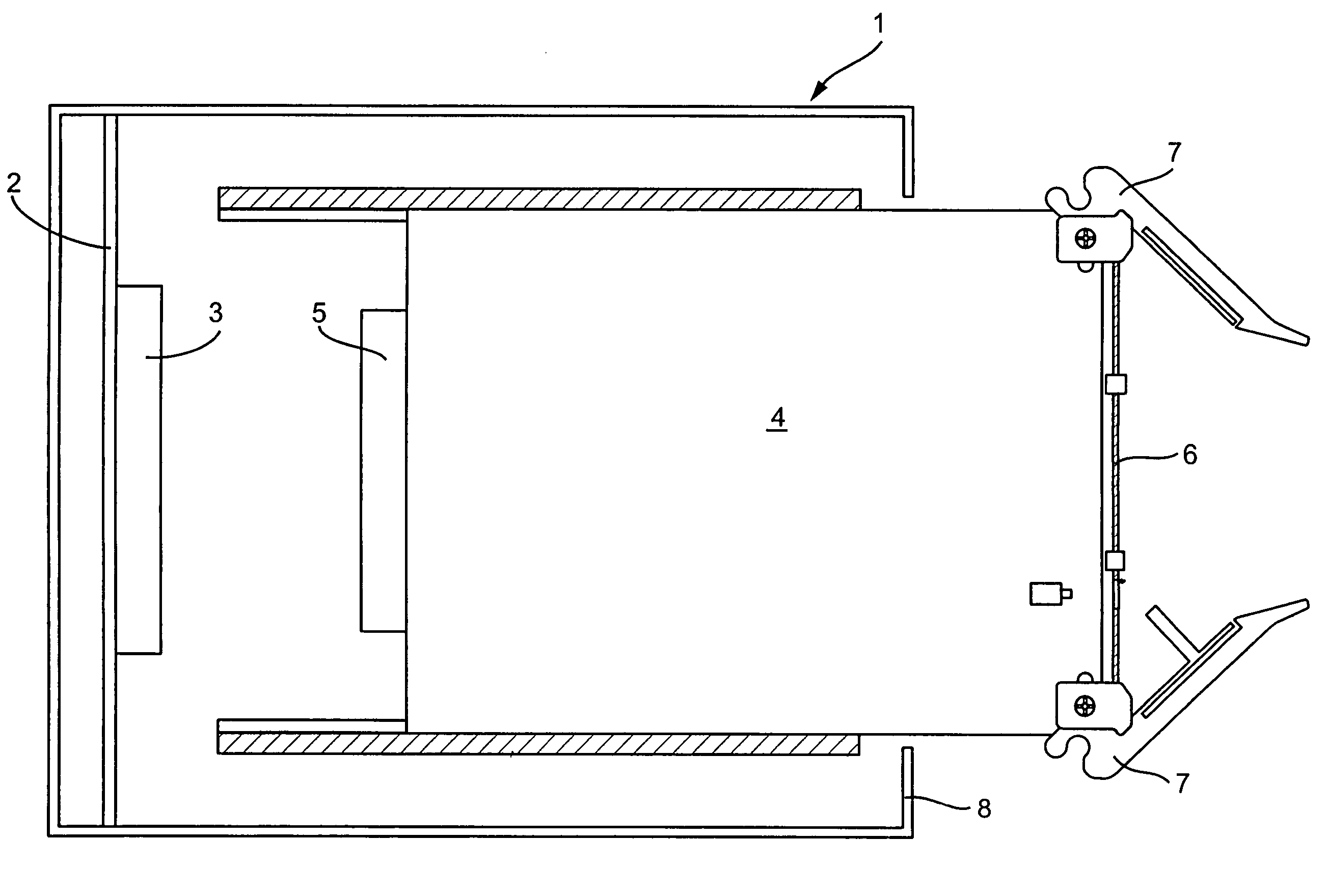
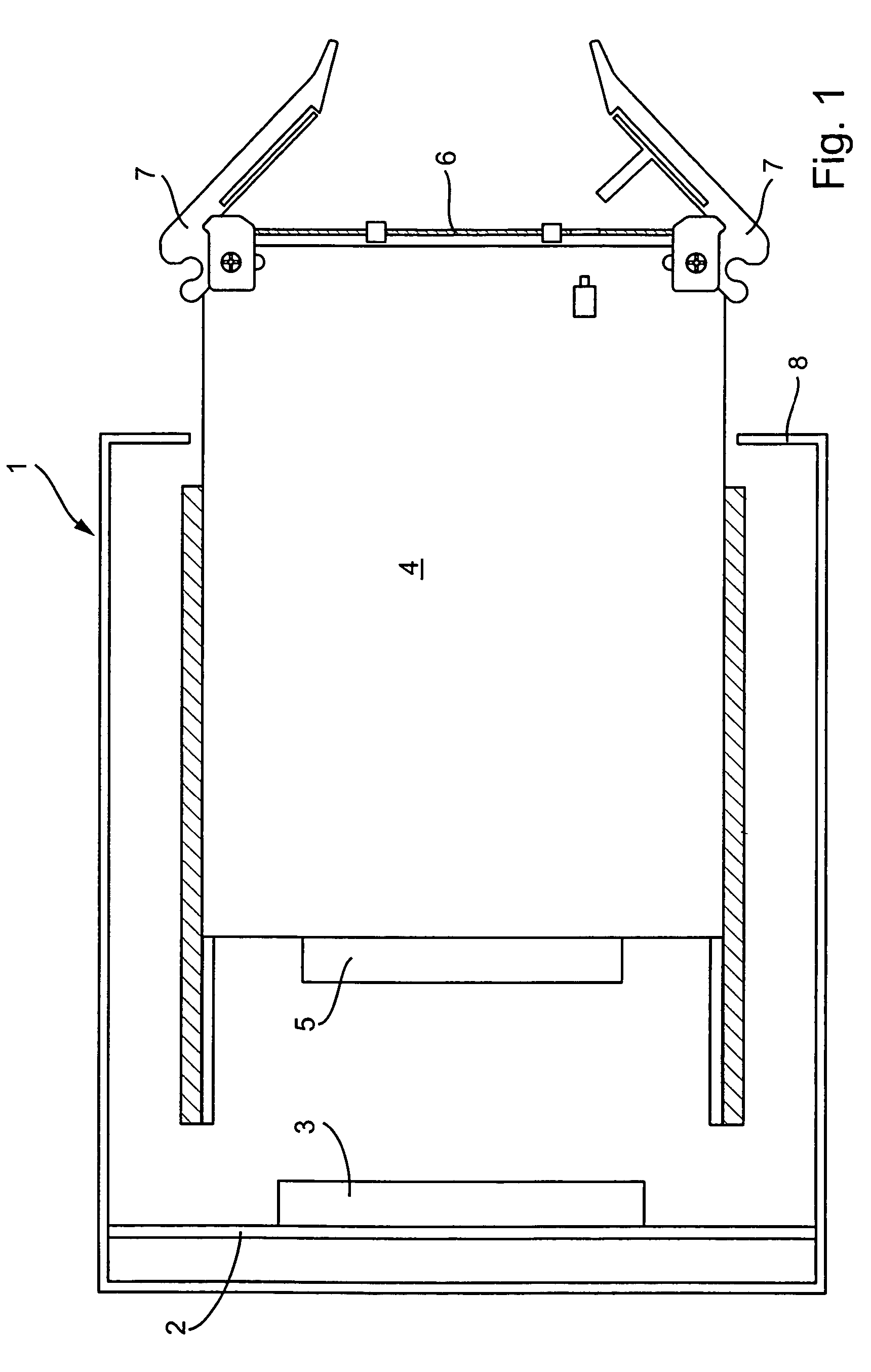
[0034]FIG. 1 illustrates a rack 1 whose rear region is composed of a back wired circuit board 2. A multi-way connector 3 is provided on the back-wired circuit board 2. A plug-in circuit board 4 has a plug 5 on its back side that produces a connection with the multi-way connector 3 in the installed state of the plug-in circuit board 4.

[0035]The plug-in circuit board 4 includes a front plate 6 in its frontal region. Upper and lower lever-latch handles 7 are located at the upper and lower corners of the front plate 6. To push the plug-in circuit board 4 into or pull it out of the rack 1, the lever-latch handles 7 engage a front, profile rail or wall 8 of the rack 1.

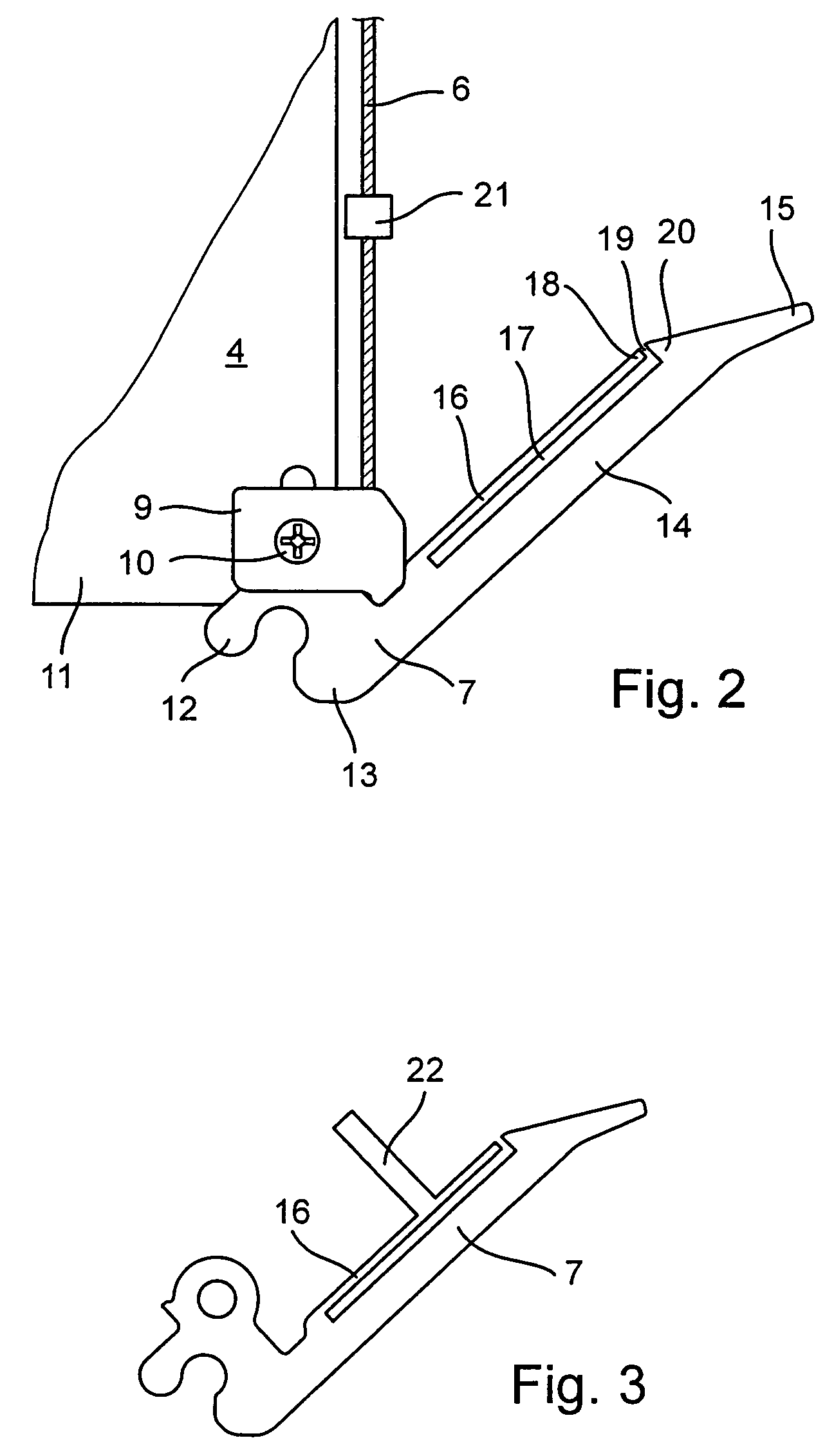
[0036]FIG. 2 shows in detail the lower front corner of the plug-in circuit board 4 with the lower lever-latch handle 7. The lower front corner of the plug-in circuit board 4 is provided with an attachment adapter 9. Th...


PUM


Abstract

A plug-in circuit board for insertion into and withdrawal from a rack having at least one front profile rail includes a front plate and a lever-latch handle with a gripping bar pivotably-mounted to the front of the plug-in circuit board. The gripping bar includes an elastically deflectable tongue which, in the pushed-in state of the plug-in circuit board, engages the front plate by a magnetic force between a magnetized stop on the front plate and the tongue.

Description

BACKGROUND OF THE INVENTION[0001]The present invention pertains to a plug-in circuit board for insertion into and withdrawal from a rack which has at least one front profile rail, the circuit board including a front plate and a pivotably-mounted, lever-latch handle with a gripping bar.[0002]In order to insert a plug-in circuit board into a rack, or in order to pull it out again from the rack, push in and pull out devices have long been known in the art. In the past various types of lever-latch handles and levers have been developed for insertion and removal of the plug-in circuit board. The forces to be applied for insertion and removal depend in large measure on the number of poles and plug connectors located on the back side of the plug-in circuit board and that are connected to corresponding plug-in connectors on the so called backplane of the rack. These multi-way connectors have, in recent times, been provided with an increased number of pins, so that the forces to be applied f...

Claims


Application Information

Patent Timeline
Patent Type & Authority Patents(United States)
IPC IPC(8): H01R13/62
CPCH05K7/1409H05K7/1414
Inventor GUNTHER, HANS-ULRICHHAAG, VOLKERHAUBER, STEFANJOIST, MICHAELPFEIFER, KLAUS
Owner SCHROFF GMBH
Why Eureka
Try Eureka