Warp knitting machine

A warp knitting machine and motor technology, applied in the field of warp knitting machines, can solve the problems of unfavorable machine power, high cost, and limited working speed of warp knitting machines, etc., and achieve the effect of reducing space requirements and extending service life

Active Publication Date: 2017-08-18
KARL MAYER STOLL R&D GMBH
View PDF9 Cites 2 Cited by
  • Summary
  • Abstract
  • Description
  • Claims
  • Application Information

AI Technical Summary

Problems solved by technology

The lateral connection via the motor cradle is susceptible to vibrations and is disadvantageous in terms of machine dynamics
In the case of a simple design structure, from which arises a limitation on the working speed of the warp knitting machine
If higher operating speeds are desired, the design becomes more complicated and thus more expensive

Method used


Image

  • Warp knitting machine
  • Warp knitting machine
  • Warp knitting machine

Examples


Embodiment Construction

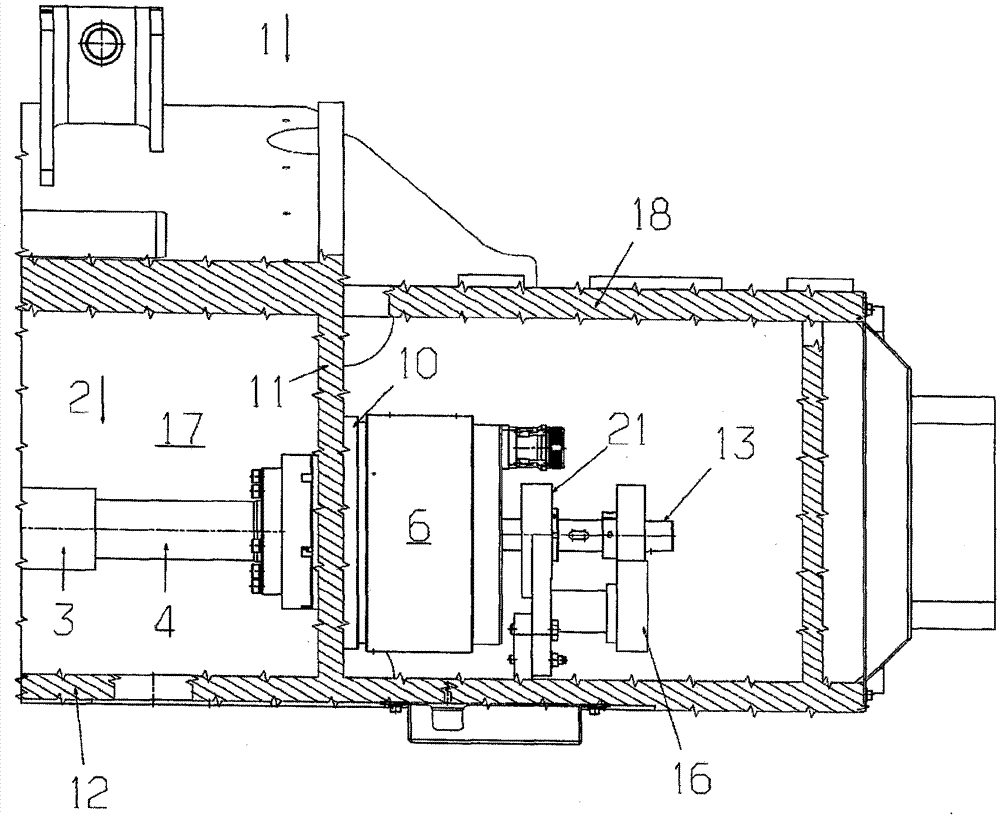
[0028] picture 1 A warp knitting machine is shown in section from above 1 the end of.

[0029] The warp knitting machine 1 with spindle 2 , the spindle has as the working section 3 to form the first segment and as terminal axis 4 to form the second segment. in the working area 3 In a manner not shown in detail above, a crankshaft transmission is fixed, which is used to drive the bar, wherein the bar supports the stitching tool in a known manner.

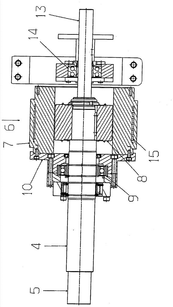
[0030] The working section 3 and the terminal axis 4 are rigidly but releasably connected to one another. as can be seen from Fig. 2 As seen in the terminal shaft 4 For this purpose there is a section with a reduced diameter 5 , the segment can be inserted into the spindle 2 working section 3 and then work with the section 3 connected.

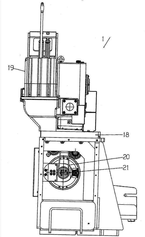
[0031] In addition, the warp knitting machine 1 with drive motor 6 , the drive motor and the drive shaft 2 arranged coaxially. The driv...


PUM


Abstract

The invention relates to a chain knitting machine (1) having a main shaft (2) and a main shaft drive which has a drive motor (6), the main shaft (2) controlling at least one bar arrangement. In such a chain knitting machine, a high working speed with a simple construction would be possible. For this purpose, it is provided that the drive motor 6 is arranged coaxially with the main shaft (2).

Description

technical field [0001] The invention relates to a warp knitting machine with a spindle and a spindle drive with a drive motor, wherein the spindle actuates at least one bar arrangement. Background technique [0002] During operation of the warp knitting machine, the main shaft is rotated and drives at least one bar, but usually a plurality of bars, for example via a crank drive, on which a looping tool is fixed. The crank gear can have a plurality of sections distributed over the length of the bar. [0003] The known drive motor is arranged laterally next to the spindle, ie the axis of rotation of the drive motor runs parallel to the axis of rotation of the spindle. The torque-transmitting connection between the drive motor and the spindle takes place via a belt or a chain. The lateral connection via the motor rocker is susceptible to vibrations and is disadvantageous in terms of machine dynamics. In the case of a simple construction, this results in a limitation of ...

Claims


Application Information

Patent Timeline
Patent Type & Authority Applications(China)
IPC IPC(8): D04B27/24D04B27/26D04B27/00H02K7/14
CPCD04B27/00D04B27/24D04B27/26H02K7/14D04B27/08
Inventor O.弗利克S.霍曼J.布卢默C-P.灿格T.格罗布
Owner KARL MAYER STOLL R&D GMBH
Why Eureka
Try Eureka