Warp knitting machine

A warp knitting machine and control mechanism technology, applied in the field of warp knitting machines, can solve problems such as increased working speed and increased loss, and achieve the effects of increasing production speed and large working range

Inactive Publication Date: 2017-08-18
KARL MAYER R&D GMBH
View PDF9 Cites 2 Cited by
  • Summary
  • Abstract
  • Description
  • Claims
  • Application Information

AI Technical Summary

Problems solved by technology

This loss increases with increasing operating speed, so that said loss forms a

Method used


Image

  • Warp knitting machine
  • Warp knitting machine
  • Warp knitting machine

Examples


Embodiment Construction

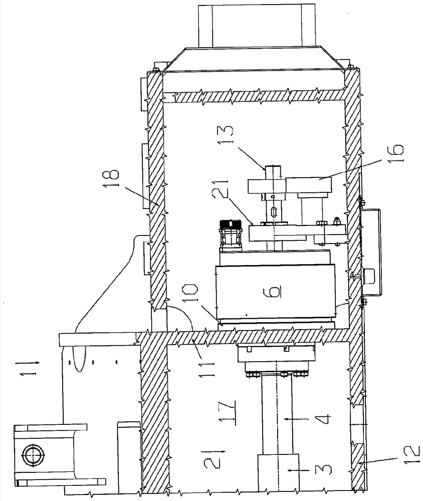
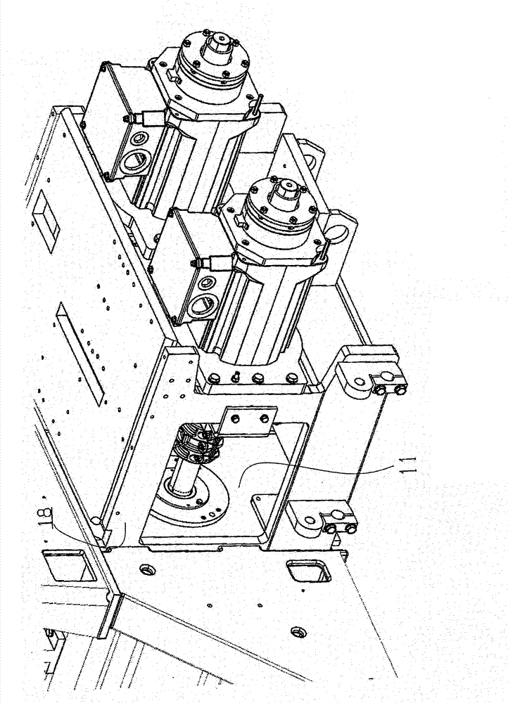
[0022] image 3 The end of one half of the warp knitting machine 1 is shown in section from above.

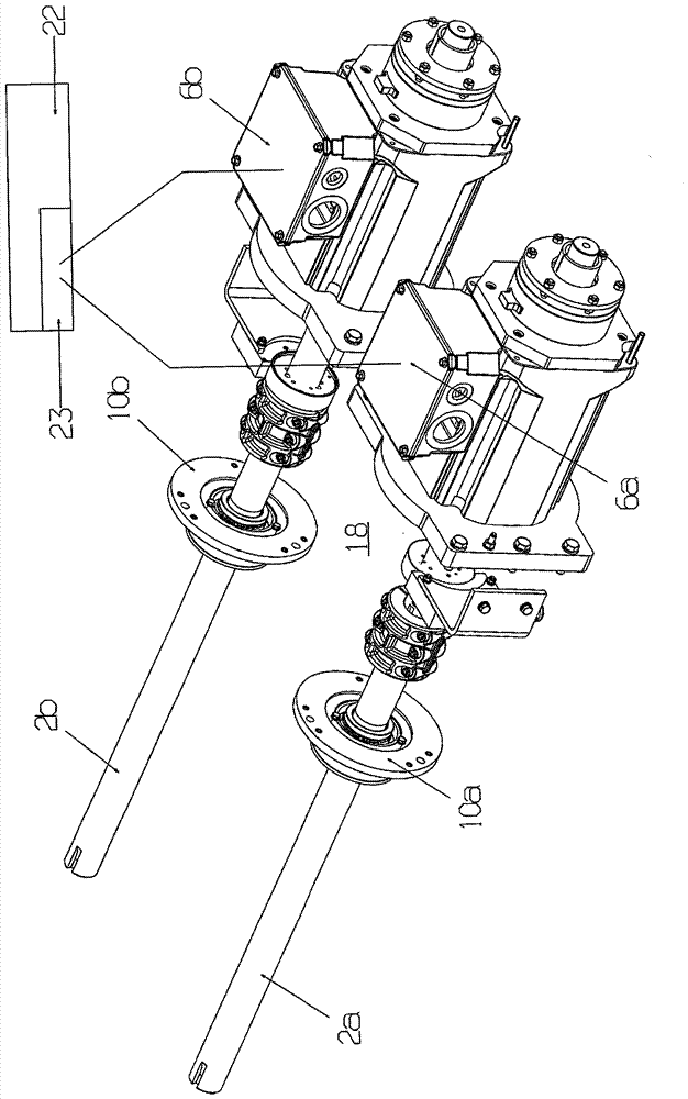
[0023] The warp knitting machine 1 has a spindle 2 with a first section configured as a working section 3 and a second section configured as an end shaft 4 . In a manner not shown in greater detail, a crank drive for driving the bar, which carries the stitching tool in a known manner, is fixed on the working section 3 .

[0024] The working section 3 and the end shaft 4 are connected rigidly, but detachably, to one another. as from Figure 4 As can be seen in , the terminal shaft 4 also has a section 5 with a reduced diameter, which can be inserted into the working section 3 of the main shaft 2 and then connected to the working section 3 .

[0025] The spindle 2 is connected to a drive motor 6 which is arranged coaxially with the spindle 2 . The drive motor 6 is directly connected to the spindle 2 , ie without intervening gears or gear stages, wherein this connectio...


PUM


Abstract

The invention relates to a chain knitting machine (1) having at least two main shafts (2a, 2b), each of which actuates at least one bar assembly. One would like to specify a high-productivity chain knitting machine. For this purpose, it is provided that each main shaft (2a, 2b) is in drive connection with its own drive motor (6a, 6b).

Description

technical field [0001] The invention relates to a warp knitting machine having at least two main shafts, wherein each main shaft handles at least one bar arrangement. Background technique [0002] During operation of the warp knitting machine, the main shaft rotates and drives at least one bar, usually a plurality of bars, for example via a crankshaft drive, to which loop forming tools are fastened. The crank gear can have a plurality of sections distributed over the length of the bar. [0003] In warp knitting machines with more than one spindle, the spindles must be driven in a certain dependence on one another. This is currently solved by a gear mechanism which forms the connection between the spindles. The transmission often has a belt which transmits the rotational movement from one spindle to the other. [0004] During operation of the warp knitting machine, a load change occurs with one revolution of the spindle. These load changes cause high losses. This ...

Claims


Application Information

Patent Timeline
IPC IPC(8): D04B27/24
CPCD04B27/24D04B27/08D04B35/30D04B35/28D04B35/00D04B37/06
Inventor M.奥特R.桑德曼O.弗利克S.厄尔斯特伦J.利斯特M.里斯G.埃特格斯
Owner KARL MAYER R&D GMBH
Why Eureka
Try Eureka