Rotatively driving apparatus
a technology of rotating apparatus and driving shaft, which is applied in the direction of electric propulsion mounting, transportation and packaging, gearing, etc., can solve the problems of deteriorating weight balance between the left and right sides of the four-wheel drive vehicle, large apparatus size, etc., and achieve the effect of improving weight balance and satisfying weight balan
- Summary
- Abstract
- Description
- Claims
- Application Information
AI Technical Summary
Benefits of technology
Problems solved by technology
Method used
Image

Examples
first embodiment
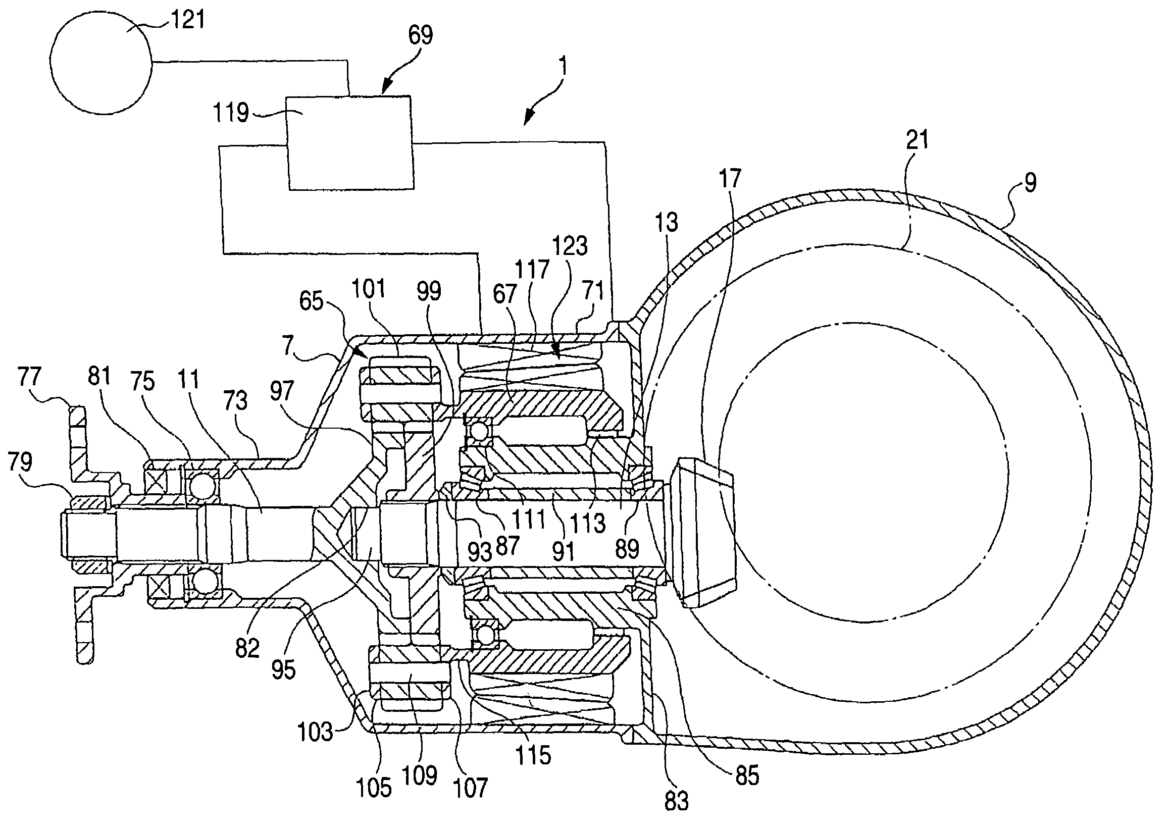
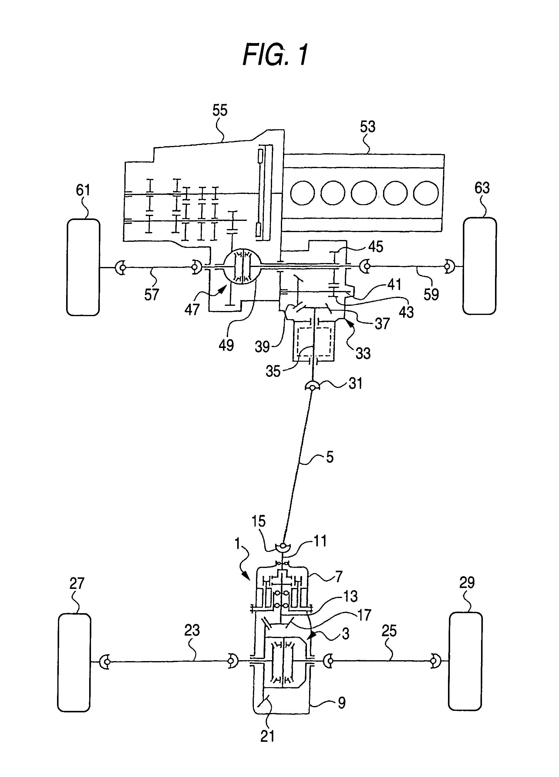
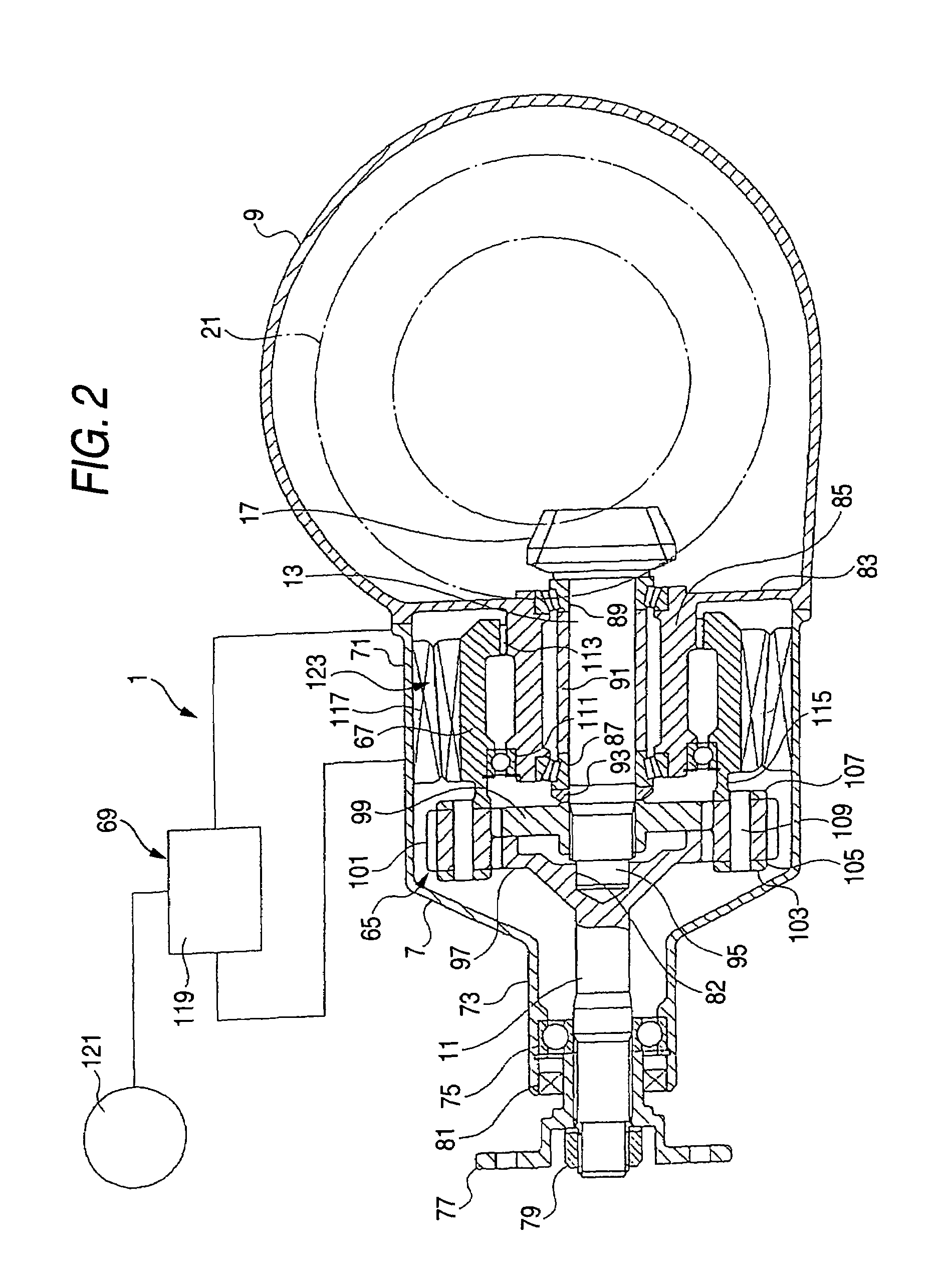
[0035]FIGS. 1 to 3 are diagrams illustrating a first embodiment of the invention, in which FIG. 1 is a skeleton plan view of a four-wheel drive vehicle illustrating the arrangement of a rotatively driving apparatus, FIG. 2 is an enlarged cross-sectional view illustrating the rotatively driving apparatus and its periphery, FIG. 3 is an enlarged cross-sectional view of essential portions, and FIG. 4 is a graph illustrating a relationship between a differential rotation and a transmitted torque.
[0036]As shown in FIG. 1, a rotatively driving apparatus is disposed between a rear differential gear 3 and a propeller shaft 5 of a four-wheel drive vehicle of a front-engine front-drive base (FF base), in which the engine has a crank shaft extending in lateral direction of the vehicle. The rotatively driving apparatus 1 is disposed in a carrier cover 7 (a casing 7). The carrier cover 7 is mounted on a differential carrier 9.
[0037]As two relatively rotatable members both of which rotate, the ro...
second embodiment
[0079]FIGS. 5 and 6 are diagrams illustrating a second embodiment of the invention, in which FIG. 5 is an enlarged cross-sectional view illustrating the rotatively driving apparatus and its periphery, and FIG. 6 is an enlarged cross-sectional view of essential portions. It should be noted that a description will be given by denoting component portions corresponding to those of the first embodiment by the same reference numerals.
[0080]In this embodiment, a differential rotation amplification mechanism 65A of a rotatively driving apparatus 1a is constructed by a planetary gear mechanism. Namely, the differential rotation amplification mechanism 65A consists of an internal gear 125, a sun gear 127, planetary gears 129, and a carrier 131.
[0081]The internal gear 125 is provided on a cylinder portion 135. The cylinder portion 135 is provided on an outer periphery of a flange portion 133 provided on an end portion of the rotating shaft 11. The sun gear 127 is provided on an inner cylinder ...
third embodiment
[0089]FIGS. 7 and 8 are diagrams illustrating a third embodiment of the invention, in which FIG. 7 is an enlarged cross-sectional view illustrating the rotatively driving apparatus and its periphery, and FIG. 8 is an enlarged cross-sectional view of essential portions. It should be noted that a description will be given by denoting component portions corresponding to those of the first embodiment by the same reference numerals.
[0090]In this embodiment, a rotation controlling mechanism 69B using a friction plate is used. Namely, the rotation controlling mechanism 69B has a fastening portion 149 and a pump portion 151 (an actuator 151).
[0091]The fastening portion 149 is provided between a rotor 67B and a large-diameter portion 71B of a carrier cover 7B (a casing 7B), i.e., the fixed side, and limits the rotation of the rotor 67B with respect to the large-diameter portion 71B by fastening. Namely, the fastening portion 149 has a multiple disk friction clutch 153, a pressure receiving p...
PUM
 Abstract
Description
Claims
Application Information
 - R&D
- Intellectual Property
- Life Sciences
- Materials
- Tech Scout
- Unparalleled Data Quality
- Higher Quality Content
- 60% Fewer Hallucinations
Browse by: Latest US Patents, China's latest patents, Technical Efficacy Thesaurus, Application Domain, Technology Topic, Popular Technical Reports.
© 2025 PatSnap. All rights reserved.Legal|Privacy policy|Modern Slavery Act Transparency Statement|Sitemap|About US| Contact US: help@patsnap.com