Component heater

a heater and component technology, applied in the direction of lighting and heating apparatus, instruments, containers, etc., can solve the problems of rendering the valve inoperable and rendering it inoperabl

Active Publication Date: 2008-11-25
VERSUM MATERIALS US LLC
View PDF20 Cites 25 Cited by
  • Summary
  • Abstract
  • Description
  • Claims
  • Application Information

AI Technical Summary

Benefits of technology

[0004]In one embodiment, the heat conducting body comprises a metal block and the heating element comprises an electrical resistive heater. In this embodiment, a cavity is positioned within the massive portion of the body. The cavity receives the electrical resistive heater, which is sealed within the cavity using an inert compound. This isolates the electrically resistive heater from the ambient to prevent ignition of explosive or flammable gases thus allowing the heater to be used in hazardous environments. The heating element may include a temperature sensor, for example a thermocouple, for controlling the temperature of the device. An insulating shroud is positioned surrounding the heat conducting body to prevent heat from escaping to the ambient and being wasted, thus conserving energy.

Problems solved by technology

The cooling can be significant and cause the moving parts of the valve to contract and jam, rendering the valve inoperable.
Furthermore, moisture in the air within and surrounding the valve may condense and freeze within and / or on the valve, also rendering it inoperable.

Method used


Image

  • Component heater
  • Component heater
  • Component heater

Examples


Embodiment Construction

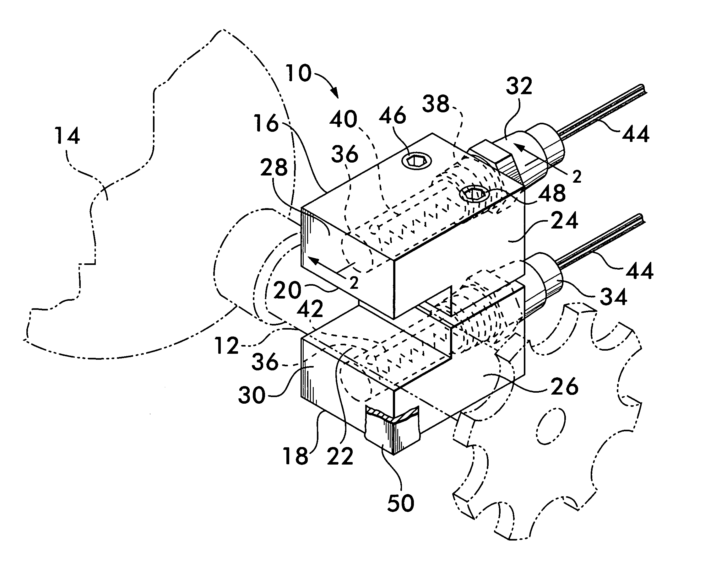
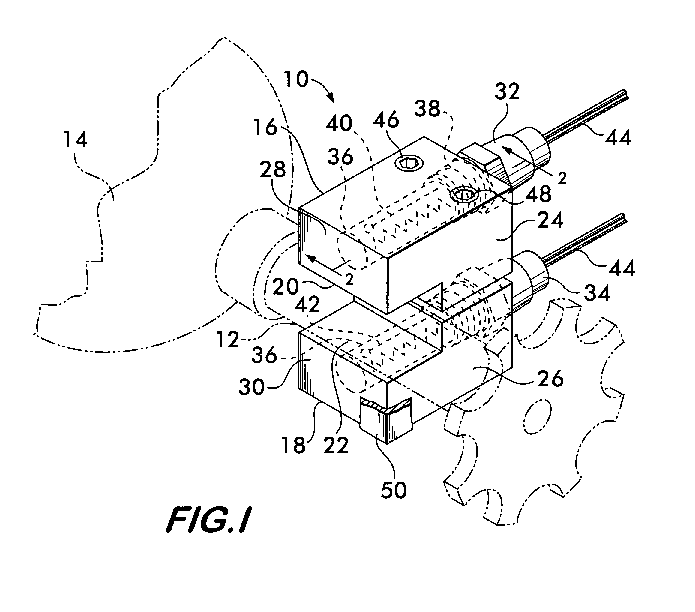
[0012]FIG. 1 illustrates a heating device embodiment 10 according to the invention in position surrounding a valve 12 on a gas cylinder 14, shown in phantom line. Heater 10 has a pair of jaws 16 and 18 formed from blocks of a heat conducting material, such as metal. Aluminum, brass, copper and steel are examples of metals that may be used to good effect to form the jaws. Each jaw has a heat transfer surface, 20 and 22 respectively (see also FIG. 2). The surfaces engage the valve 12 or other component to be heated, and effect heat transfer to the valve mainly through conduction. Each jaw 16 and 18 also has a massive portion, 24 and 26 respectively, which serve as heat reservoirs. The heat reservoirs, by virtue of their relatively large mass, allow the heater 10 to accommodate sudden and rapid heat transfer transients, as may be occasioned by the sudden and prolonged opening of the valve, while maintaining a relatively stable demand for electrical power. The reservoirs also mitigate l...


PUM


Abstract

A heater for fluid flow components. The heater has heat transfer surfaces that engage the component. The transfer surfaces are mounted on jaws that are movable to engage the component. The jaws have massive portions that act as heat reservoirs to maintain a constant temperature in spite of rapid cooling when gas is allowed to expand freely from the component. The jaws are heated by electrical resistive heating elements that are sealingly mounted within the massive portions. The sealing engagement allows the heater to be used in hazardous environments.

Description

BACKGROUND OF THE INVENTION[0001]The invention relates to devices for heating components such as valves, fittings, or other items related to controlling fluid flow.[0002]Many industrial and commercial processes use compressed gas supplied from a reservoir, such as a tank or gas cylinder. The flow of gas from the reservoir, for example, a cylinder, is controlled by a valve, usually mounted directly on the cylinder. When a compressed gas is permitted to expand freely through a throttling device such as a valve, it undergoes the Joule-Thomson effect, a process by which the gas temperature increases or decreases during free expansion at constant enthalpy (no work extracted from the gas, no heat transfer to or from the gas). For most gases used in industrial applications, the conditions of pressure and temperature are such that the Joule-Thomson effect causes the gas to cool as it is released from the cylinder. The cooling can be significant and cause the moving parts of the valve to con...

Claims


Application Information

Patent Timeline
Patent Type & Authority Patents(United States)
IPC IPC(8): H05B3/44
CPCF16K49/002F17C13/04F17C2205/0323F17C2201/0109F17C2205/0329F17C2227/0304F17C2227/0383F17C2250/032F17C2250/0631F17C2250/0636F17C2260/032F17C13/00
Inventor GERVER, LESTER S.HOPKINS, CHRISTOPHER DAVIDGERSHTEIN, VLADIMIR YLIY
Owner VERSUM MATERIALS US LLC
Why Eureka
Try Eureka