Large aperture rectenna based on planar lens structures

a planar lens and large aperture technology, applied in the direction of antennas, antenna details, antenna adaptation in movable bodies, etc., can solve the problems of limiting the lifespan of the device, unable to easily supply high-energy bursts without significant additional, and limited the amount of weight it can carry

Active Publication Date: 2008-11-25
HRL LAB
View PDF202 Cites 53 Cited by
  • Summary
  • Abstract
  • Description
  • Claims
  • Application Information

AI Technical Summary

Problems solved by technology

Presently, power sources are limited to solar panels or on-board power supplies.
Furthermore, a system of solar panels and/or on-board sources is best suited to continuous power at moderate levels, and cannot easily supply high-energy bursts without significant additional weight in order to collect and store, and then release the energy.
As the size of a UAV is reduced, the amount of weight that it can carry limits its lifespan significantly.
For example, 100-gram airplanes have been built, but their lifetime is limited to six minutes with currently available batteries.
This has several drawbacks, including scattering by atmospheric turbulence and airborne particles, the typically low wall-plug efficiencies of lasers compared to microwave sources, and the losses in conversion back to DC by photovoltaic cells.
Lasers may be viable alternatives for stationary, near-earth applications such as zeppelins, but not for moving applications, such as micro-UAVs.
Their utility fo

Method used


Image

  • Large aperture rectenna based on planar lens structures
  • Large aperture rectenna based on planar lens structures
  • Large aperture rectenna based on planar lens structures

Examples


Embodiment Construction

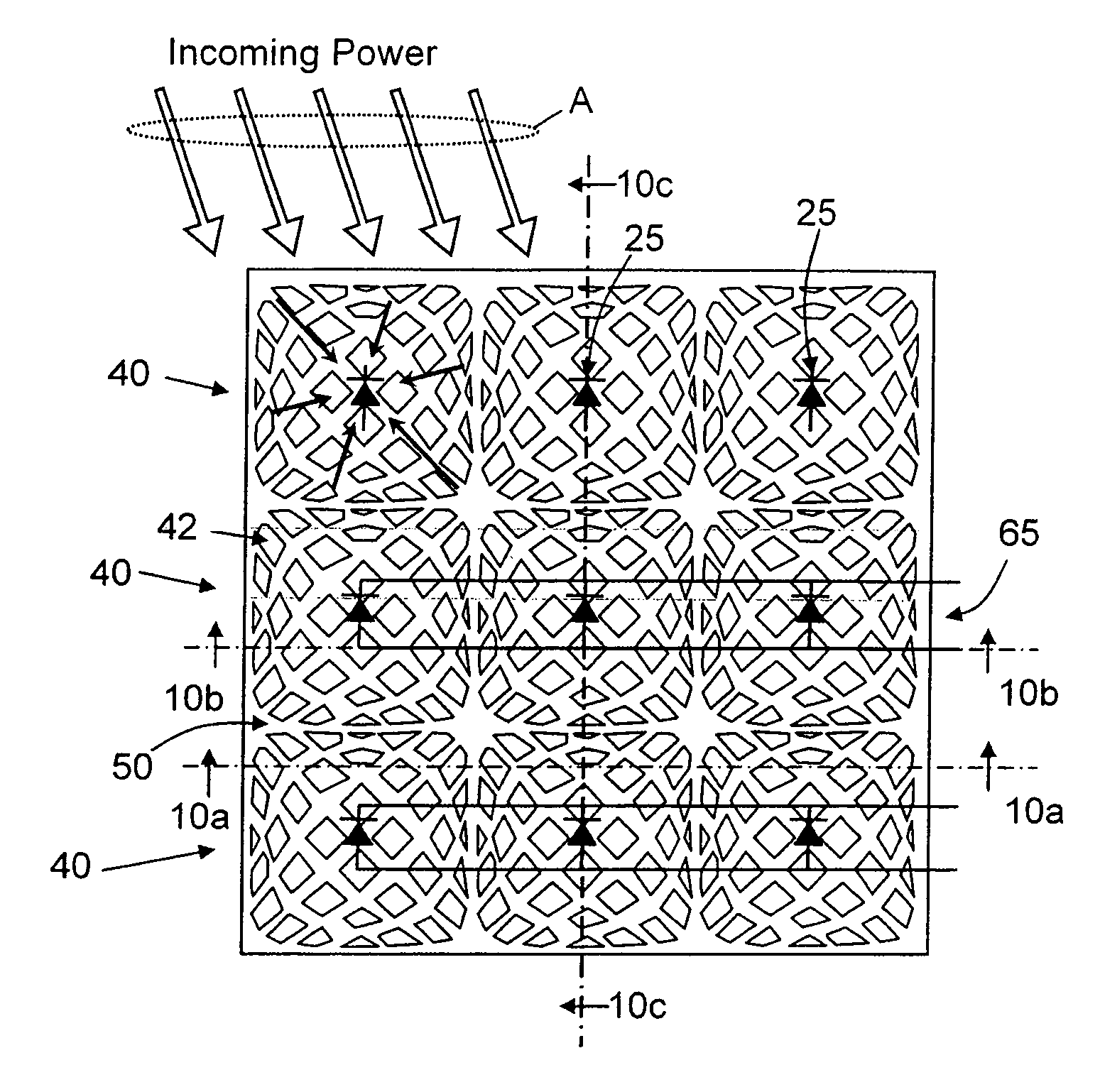
[0057]A problem in trying to develop a practical earth to space power transmission system is that the voltage across diodes used in a rectenna has not been sufficient in a prior art rectenna to be of practical use to such an application.

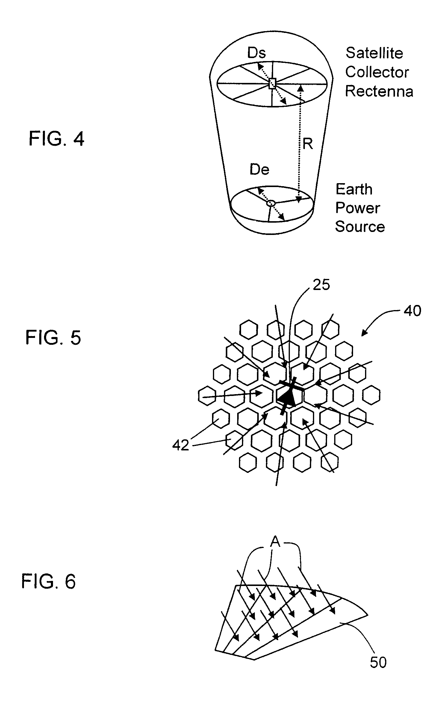
[0058]However, the voltage across each diode 25 can be increased while reducing the number of diodes by using a lens-like structure or lenslet 40, shown in FIG. 5, to concentrate power from a large area over a small number of diodes 25 in an array of lenslets 40. For example, if one wanted to generate 20 volts across each diode 25, then the incident power from 40 square wavelengths, or a 2-cm diameter area, needs to be collected. This would not only boost the voltage across each diode—and also the diode's efficiency—it would also reduce the number of diodes to about 3 million for the example described above, which equates to about 100 wafers' worth of diodes. Further reductions in the number of diodes required could be achieved with an even larger co...


PUM


Abstract

A rectenna structure comprising a flexible, dielectric sheet of material; a plurality of metallic lenslets disposed on the sheet of material; and a plurality of diodes disposed on the sheet of material, each diode in said plurality of diodes being arranged at a focus of a corresponding one of said plurality of metallic lenslets.

Description

CROSS-REFERENCE TO RELATED APPLICATIONS[0001]This patent application is a divisional application of U.S. application Ser. No. 10 / 994,032, filed Sep. 17, 2004 now U.S. Pat. No. 7,154,451 which claims the benefit of U.S. Provisional Application Ser. No. 60 / 470,027 entitled “Meta-element Antenna and Array” filed May 12, 2003 and to U.S. Patent Application Ser. No. 60 / 470,028 entitled “Steerable Leaky Wave Antenna Capable for Both Forward and Backward Radiation” filed May 12, 2003. The disclosures of these applications are hereby incorporated herein by reference. This disclosure is also related to two non-provisional applications that were filed claiming the benefit of the aforementioned applications. The two non-provisional applications have Ser. Nos. 10 / 792,411 (now U.S. Pat. No. 7,068,234 issued Jun. 27, 2006) and 10 / 792,412 and were both filed on Mar. 2, 2004. The disclosures of these two non-provisional applications are also incorporated herein by reference.TECHNICAL FIELD[0002]The...

Claims


Application Information

Patent Timeline
IPC IPC(8): H01Q15/02
CPCH01Q15/02H01Q15/0066H01Q15/147
Inventor SIEVENPIPER, DANIEL F.
Owner HRL LAB
Why Eureka
Try Eureka