
Magnetostrictive transmitter with improved piezoelectric sensor

a piezoelectric sensor and magnetostrictive technology, applied in the direction of instruments, magnetic properties, liquid/fluent solid measurements, etc., can solve the problems of low amplitude signal, sensor may falsely detect spurious vibrations, difficult manufacturing, etc., and achieve the effect of improving the magnetostrictive position sensor

Active Publication Date: 2008-12-16
AMETEK MAGNETROL USA LLC
View PDF9 Cites 6 Cited by
  • Summary
  • Abstract
  • Description
  • Claims
  • Application Information

AI Technical Summary

Problems solved by technology

This can result in a noisy and low amplitude signal.
Such an arrangement is sensitive to the position of the crystals and requires fine adjustments and tuning, making it difficult to manufacture.
Such a sensor may falsely detect spurious vibrations in a magnetostrictive wire.
However, the high number of specialized crystals required to build such an assembly make it expensive.
Moreover, the inner and outer masses and bonding steps add to the total cost.

Method used


Image

  • Magnetostrictive transmitter with improved piezoelectric sensor
  • Magnetostrictive transmitter with improved piezoelectric sensor
  • Magnetostrictive transmitter with improved piezoelectric sensor

Examples


Embodiment Construction

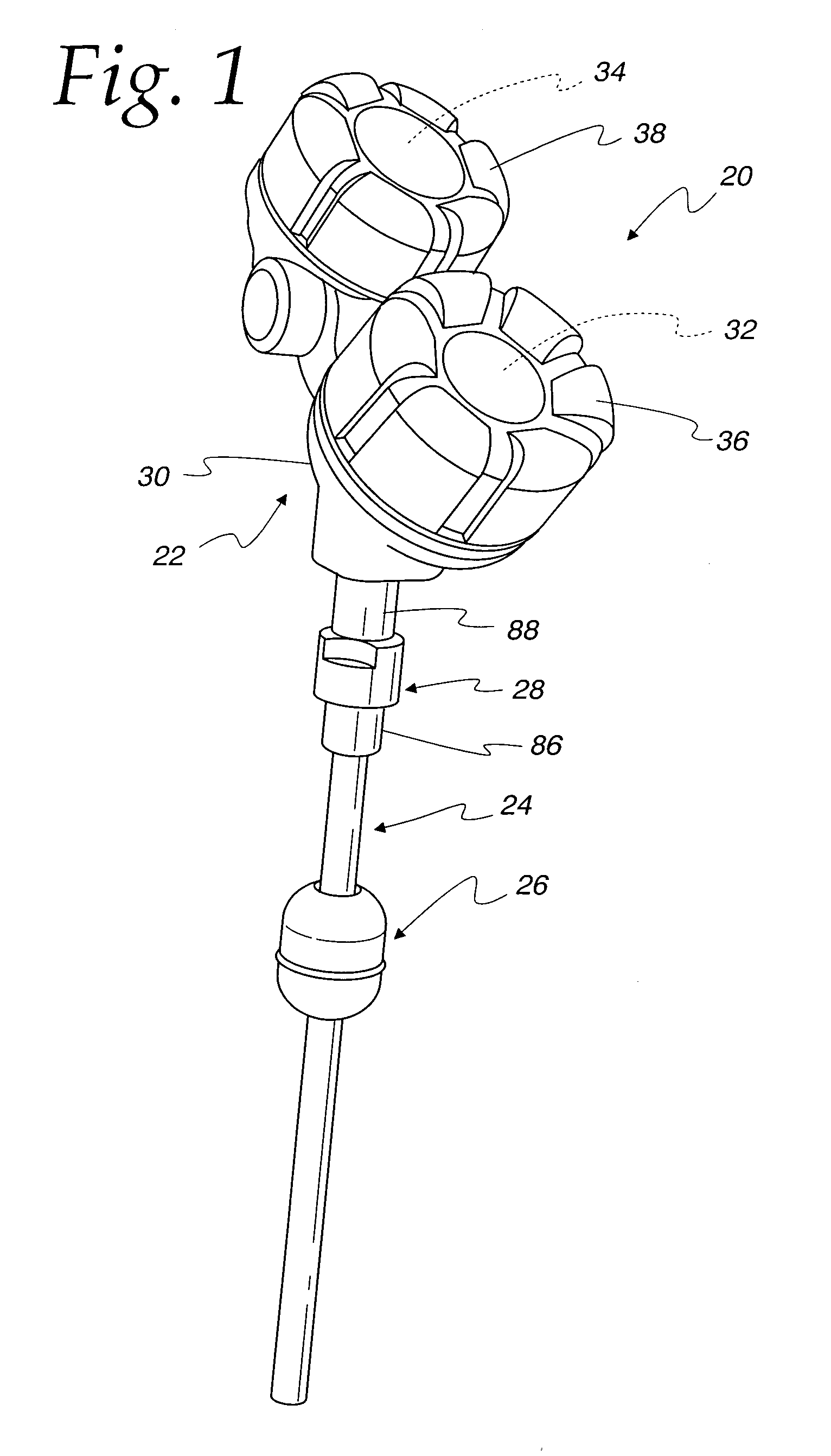
[0030]Referring to FIG. 1, a magnetostrictive level sensing instrument in the form of a transmitter 20 is illustrated. The transmitter 20 is operable to sense level of a material, such as a fluid in a process vessel, and transmit an electrical signal indicative of the level to control instrumentation.

[0031]The transmitter 20 includes a control housing 22, a probe 24, a float 26 and a connector 28 connecting the probe 24 to the housing 22. The housing 22 comprises a dual compartment instrument housing as described in Mulrooney et al. U.S. Pat. No. 6,062,095. The housing 22 includes a base assembly 30 to define an electronics compartment 32 and a wiring compartment 34 selectively closed by covers 36 and 38, respectively. The electronics compartment 32 houses a sensing circuit, described below, for determining level and generating the electrical signal representing level for transmission to other control instruments, as is well known.

[0032]The float 26 comprises a magnetic float captur...


PUM


Abstract

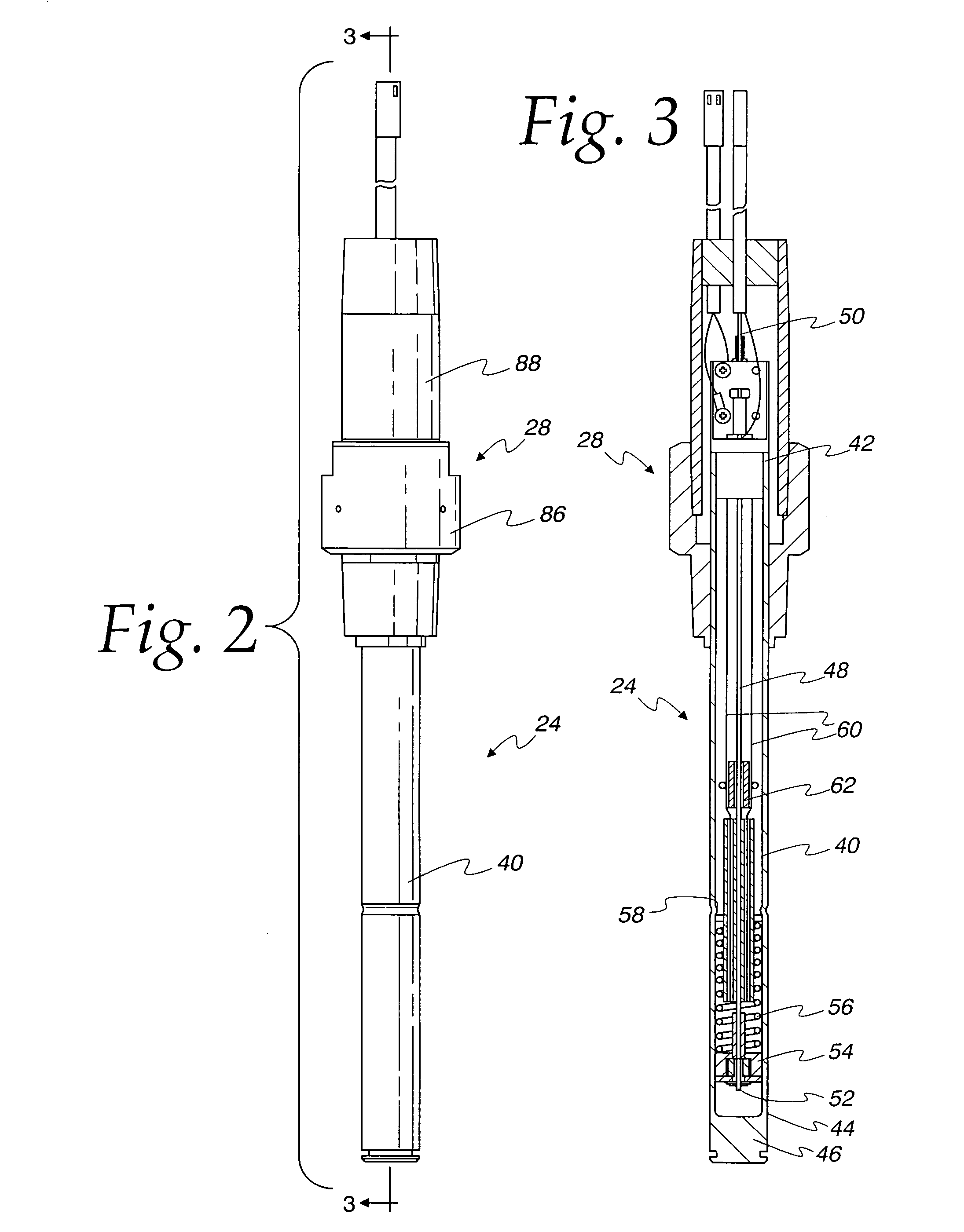
A magnetostrictive level sensing instrument is used for sensing level in a process vessel and comprises an elongate tube having a near end and a distal end. A magnet is selectively positionable proximate the tube responsive to level of the processed material. A magnetostrictive wire in the tube has first and second ends. The second end is operatively secured at the tube distal end. A pair of shear mode crystals are mounted proximate the tube near end. The crystals sandwich the magnetostrictive wire proximate the first end. A sensing circuit is operatively connected to the magnetostrictive wire and the pair of crystals for generating an electrical pulse on the magnetostrictive wire whereby a magnetic field produced by the magnet interacts with the electrical pulse to produce a torsional wave on the magnetostrictive wire sensed by the pair of crystals.

Description

CROSS REFERENCE TO RELATED APPLICATIONS[0001]There are no related applications.FIELD OF THE INVENTION[0002]The present invention relates to magnetostrictive level sensing instruments and, more particularly, to an improved piezoelectric position sensor.BACKGROUND OF THE INVENTION[0003]Sensing instruments are used for sensing various different process variables, such as level of a process fluid or material in a process vessel. Many such instruments are of the intrusive type in which a sensing apparatus is exposed to the process fluid for sensing level. One such type of intrusive sensor comprises a magnetostrictive sensor. A magnetostrictive sensor has a probe including a magnetostrictive wire maintained under tension in a tube. The probe extends into the process vessel. A magnetic float is movable proximate the probe and floats atop the fluid in the vessel. An electrical pulse is transmitted on the magnetostrictive wire. The electrical pulse interacts with the magnetic field of the fl...

Claims


Application Information

Patent Timeline
Patent Type & Authority Patents(United States)
IPC IPC(8): G01B7/14G01R33/18
CPCG01F23/2963G01F23/68G01F23/72
Inventor JANITCH, PAUL G.SUSSMAN, TIMOTHY S.
Owner AMETEK MAGNETROL USA LLC
Learn More