Device and process for manipulating real and virtual objects in three-dimensional space

a technology of three-dimensional space and devices, applied in mechanical control devices, single control member manual control, sensors, etc., can solve the problems of complex scan plane prescription, insufficient two-dimensional projection of scan plane wire-frame representation, and difficulty in performing. to achieve the effect of accurate detection

Inactive Publication Date: 2008-12-16
SUNNYBROOK HEALTH SCI CENT
View PDF11 Cites 219 Cited by
  • Summary
  • Abstract
  • Description
  • Claims
  • Application Information

AI Technical Summary

Benefits of technology

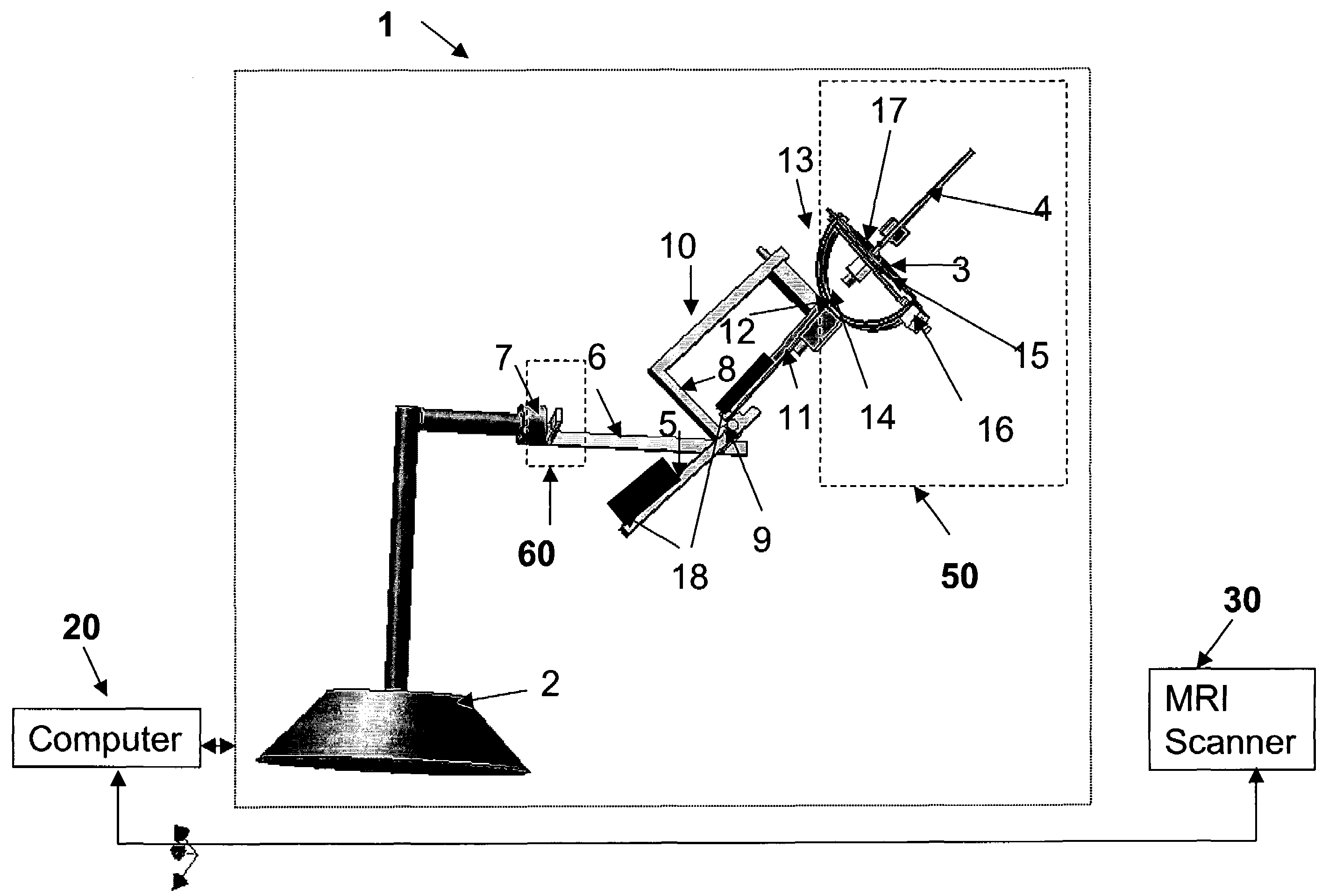
[0039]The operator can use the software system to program subsequent imaging planes based on the current image plane. The surface contained in the 6-DOF mechanical armature can move automatically to reflect the effects of the operator's action, thereby providing the operator spatial awareness in order to quickly localize the optimal scan plane. In the output mode, the software system uses inverse kinematics to automatically move the surface and stylus to a specific position and orientation, thereby providing a physical representation of virtual 3D information shown on the computer screen.
[0056]Another aspect of this invention is to provide a system for 6-DOF object manipulation and representation, wherein the position of anatomic structures in a human body can be accurately detected in magnetic resonance images.

Problems solved by technology

The operation of scan plane prescription is therefore essentially a 6-DOF task, which generally is difficult to perform because of the high dimensionality of the required operations.
Typically, a flat-screen is the only resource available to graphically indicate the location and orientation of the scan plane, compounding the problem of scan plane prescription.
A two-dimensional projection of a wire-frame representation of the scan plane is often not enough to indicate its location and orientation.
Moreover, the operator can only be certain that the last executed prescription is correct when the most recent magnetic resonance (“MR”) image is displayed.
This “try-and-see”, trial-and-error approach is time consuming and often causes frustration for human operators.
State-of-the-art scan plane prescription is relatively time consuming.
During clinical procedures, the precise placement of several scan planes is made even more difficult because of other ongoing time-limited demands experienced by the operator.
Although some currently used hardware devices such as the Spaceball are capable of providing 6-DOF input, their usage is non-intuitive, primarily because the direction and distance of 3-D translation is controlled by the force vector that the operator exerts upon the sphere.
Furthermore, current hardware devices provide inadequate visual feedback about the spatial location and orientation of the current scan plane.
Consequently, the operator does not have adequate spatial awareness and often is left with an unacceptable level of uncertainty concerning the next moving direction.
Spacemouse might have some potential for providing 6-DOF input, however, it suffers the same problem as a Spaceball, namely it returns back to a null rest station when user support is withdrawn.
The prior art does not disclose a method or device that is capable of providing input 6-DOF spatial information while also physically representing the spatial location and orientation of the object after the manipulation, which is also capable of automatically changing its position and gesture to imitate its virtual correspondence.
However, these conventional methods have fundamental problems.
First, an operator can manipulate only one degree at a time, which makes it impossible to execute a coordinated movement in 6-DOF space.
Second, human operators generally cannot mentally decompose orientation into separate rotation axes (see, for example, Zhai, Computer Graphics 32:50-54, 1998).
Consequently, given a target orientation, an operator cannot determine the rotation angles along each rotation axis required to reach the goal without first executing several “practice” attempts blindly.
This time-dependence feature makes scan plane prescription even more difficult than the operations involved in a fixed coordinate system.
Moreover, this method does not allow the user to manipulate in a coordinated manner all degrees-of-freedom at the same time.
It is well known in the art that a flat screen is not sufficient in the depth-dimension and often induces visual ambiguity.
However, most of these modified high-dimensional “flying mice” are instrumented with a magnetic tracker for 6-DOF sensing, which makes them inaccurate in the environment of MRI.
Another drawback is that the devices cannot remain at a particular location without support, which makes its difficult to resume an incomplete operation due to either fatigue or re-positioning of the hand.
There are, however, significant limitations to the inventions embodied by “Spaceball”™ and “Spacemouse”™, including insufficient feedback to the user at the kinesthetic channel (see, for example, Zhai, Computer Graphics 32:50-54, 1998).
For example, Spaceball™ is completely rigid, which presents a serious limitation because kinesthetic or proprioceptive feedback can be critical to the operator's control performance.
A second limitation of Spaceball™ is that it returns to a null-position when released giving no feedback on the current location in 3-D space of the object under manipulation.
However, unlike the present invention, the “Fingerball”™ device disclosed by Zhai et al. is not able to maintain its position when support is not provided.
Although the “MicroScribe 3D digitizer”™ can simultaneously provide 6-DOF inputs, unlike the present invention it cannot statically maintain its position or orientation.
In addition, not all of its joints can maintain balance.
Motion artifacts due to normal or abnormal respiratory movements can degrade image quality in MR scans.
However, repeated breath holding may not be feasible for many coronary patients and navigation techniques to-date have not generally provided a robust method which works over a range of different breathing patterns in a variety of patients.
Another drawback to these approaches is that success or failure is usually not apparent for some time after the start of imaging, and many times not until the imaging has been completed.
However, since the period of image acquisition is usually one to two minutes long, the images suffer from significant respiratory motion artifacts.
This then requires a manual registration and analysis of the perfusion images, which is cumbersome and time-consuming because the user must carefully arrange each image to compensate for the respiratory motion before proceeding to a region of interest time-intensity analysis.

Method used


Image

  • Device and process for manipulating real and virtual objects in three-dimensional space
  • Device and process for manipulating real and virtual objects in three-dimensional space
  • Device and process for manipulating real and virtual objects in three-dimensional space

Examples


Embodiment Construction

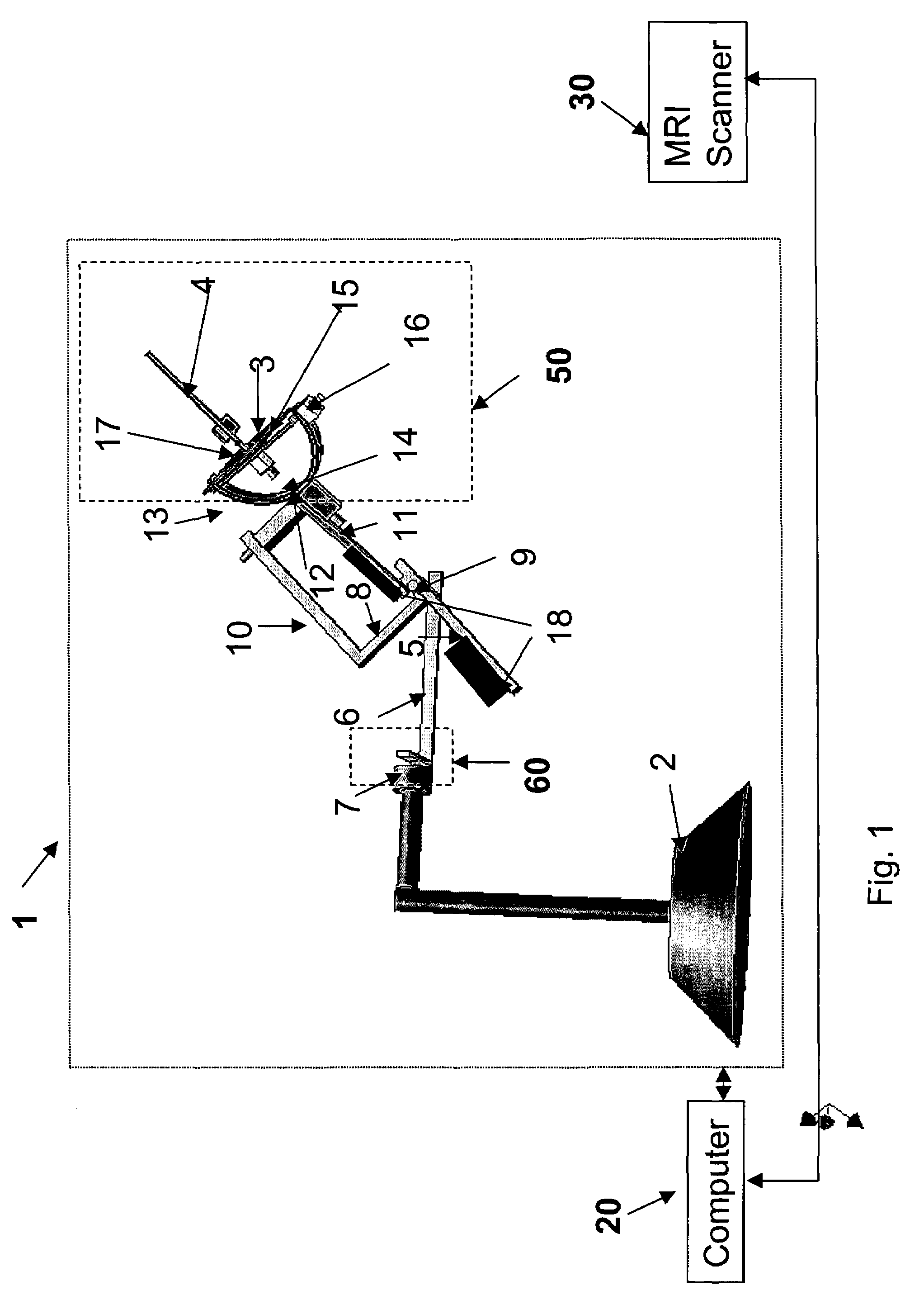
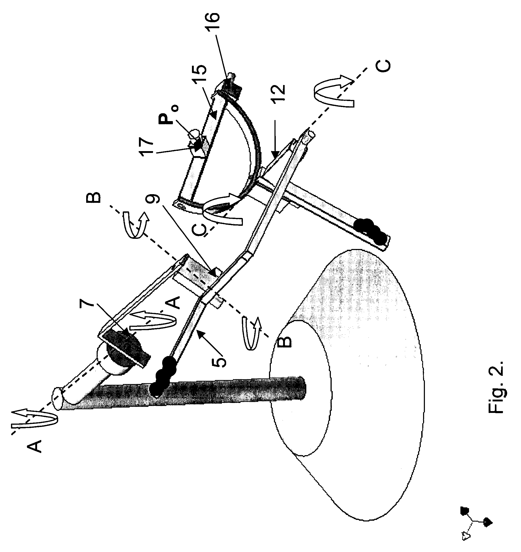
[0073]With reference to FIG. 1 of the drawings, the 6-DOF hardware disclosed by the present invention is a mechanical armature 1 consisting of six mechanical linkages that support a surface 3, and a pencil-like stylus 4 fixed to the center of the surface 3 to serve as a line perpendicular to the surface, i.e., the normal surface. In one preferred embodiment of the invention, the first linkage 6 is connected to a fixed base 2 through the first rotational joint 7 such that the first linkage can rotate along its longitudinal axis. The base 2 can be removably or permanently fixed to any one of a number of surfaces, including the surface of a desk. According to the invention, the second linkage 8 is connected to and supported by the first linkage 6 at the second rotational joint 9 and can rotate along an axis that is perpendicular to the first mechanical linkage 6. The rotation axes of the first joint 7 and the second joint 9 are perpendicular at any point in time. The third linkage 10 i...


PUM


Abstract

A device and software system with input and output capability for manipulating real and virtual objects in 3-dimensional space. The device consists of a six degree-of-freedom mechanical armature that has sensors to determine the location and orientation of a stylus and planar surface. In the input mode, manipulation of the physical armature will result in a corresponding two-dimensional, virtual image of the stylus and surface on a computer screen. The armature also has motors to automatically change the armature location and orientation in order to generate a physical representation in the real world of the location and orientation of a virtual object. The armature is built so that it maintains balance at any location and orientation to statically maintain the armature location and orientation without drifting to a null rest position.

Description

CROSS REFERENCE TO RELATED APPLICATIONS[0001]Not Applicable.FEDERAL SPONSORSHIP[0002]Not Applicable.BACKGROUND[0003]1. Field of the Invention[0004]The present invention relates to a six-degree-of-freedom mechanical armature and an integrated software system with input and output capability for manipulating real and virtual objects in three-dimensional space, and for manipulating a scan plane in magnetic resonance imaging.[0005]2. Description of Related Art[0006]Advances in medical imaging technology, including computerized tomography (CT), magnetic resonance imaging (MRI), and positron emission tomography (PET), coupled with developments in computer-based image processing and modeling capabilities, have lead to significant improvements in the ability to visualize anatomical structures in human patients. Real-time MRI inherently has advantages over conventional MRI because of its capability for rapid visualization of any scan plane and interactive adjustment of location. Interactive ...

Claims


Application Information

Patent Timeline
Patent Type & Authority Patents(United States)
IPC IPC(8): G09G5/00A61B5/055A61B6/03G05G9/047
CPCA61B5/055A61B5/7475G05G9/04737A61B5/7285G05G2009/04766
Inventor YI, DINGRONGWRIGHT, GRAHAM ARNOLDHU, BOB SUEH-CHIEN
Owner SUNNYBROOK HEALTH SCI CENT
Why Eureka
Try Eureka