Second improved electromagnetic integrative door locking device and method of installation

a technology of electromagnetic integration and door locking, applied in the direction of lock applications, instruments, individual entry/exit registers, etc., can solve the problems of gartner's lock not providing for subsequent installation within the door frame, and the electrical components are not designed for installation, so as to achieve the effect of lowering the cost per door fram

Inactive Publication Date: 2008-12-30
SHAW BARRY M
View PDF9 Cites 41 Cited by
  • Summary
  • Abstract
  • Description
  • Claims
  • Application Information

AI Technical Summary

Benefits of technology

[0027]As an electronically controlled component, my invention preferably includes a cam retaining locking bar. The cam retaining locking bar preferably contains a roll pin and an open area bordered by two cut sides. The open area eases lock installation with a door frame by avoiding protruding door structures such as metal tabs.
[0030]Another purpose of my invention is to lower the cost per door frame of upgrading existing mechanical locks with electronic security features, such as electric strikes and magnetic locks.
[0032]In addition, my new cam retaining locking bar greatly decreases a vandal's breakage of a locked door by wrenching the keyed cylinder with pliers or a wrench. These and other aspects of my invention will become apparent in the following detailed description of the preferred embodiment and other embodiments of my invention.

Problems solved by technology

However, these electrical components are not designed for installation after the mechanical locking component is installed within the doorframe.
However, Gartner's lock does not provide for subsequent installation within a doorframe of only the electronic lock component at a minimum cost and destruction of the doorframe.
Balzon's system, however, does not comprise an electronic component which can be installed subsequent to the mechanical lock unit within a door frame.

Method used


Image

  • Second improved electromagnetic integrative door locking device and method of installation
  • Second improved electromagnetic integrative door locking device and method of installation
  • Second improved electromagnetic integrative door locking device and method of installation

Examples


Embodiment Construction

Introduction

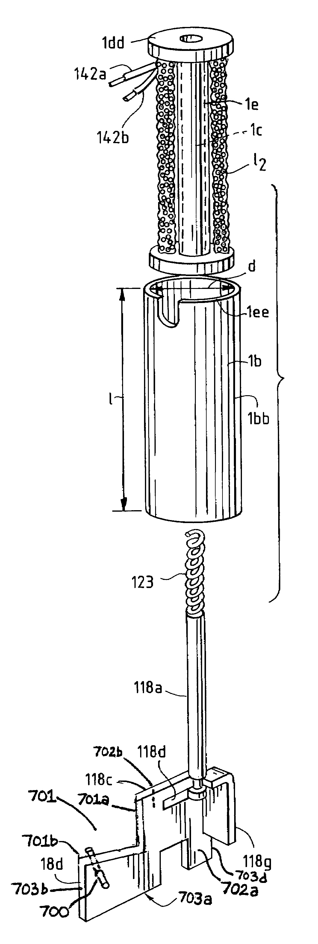
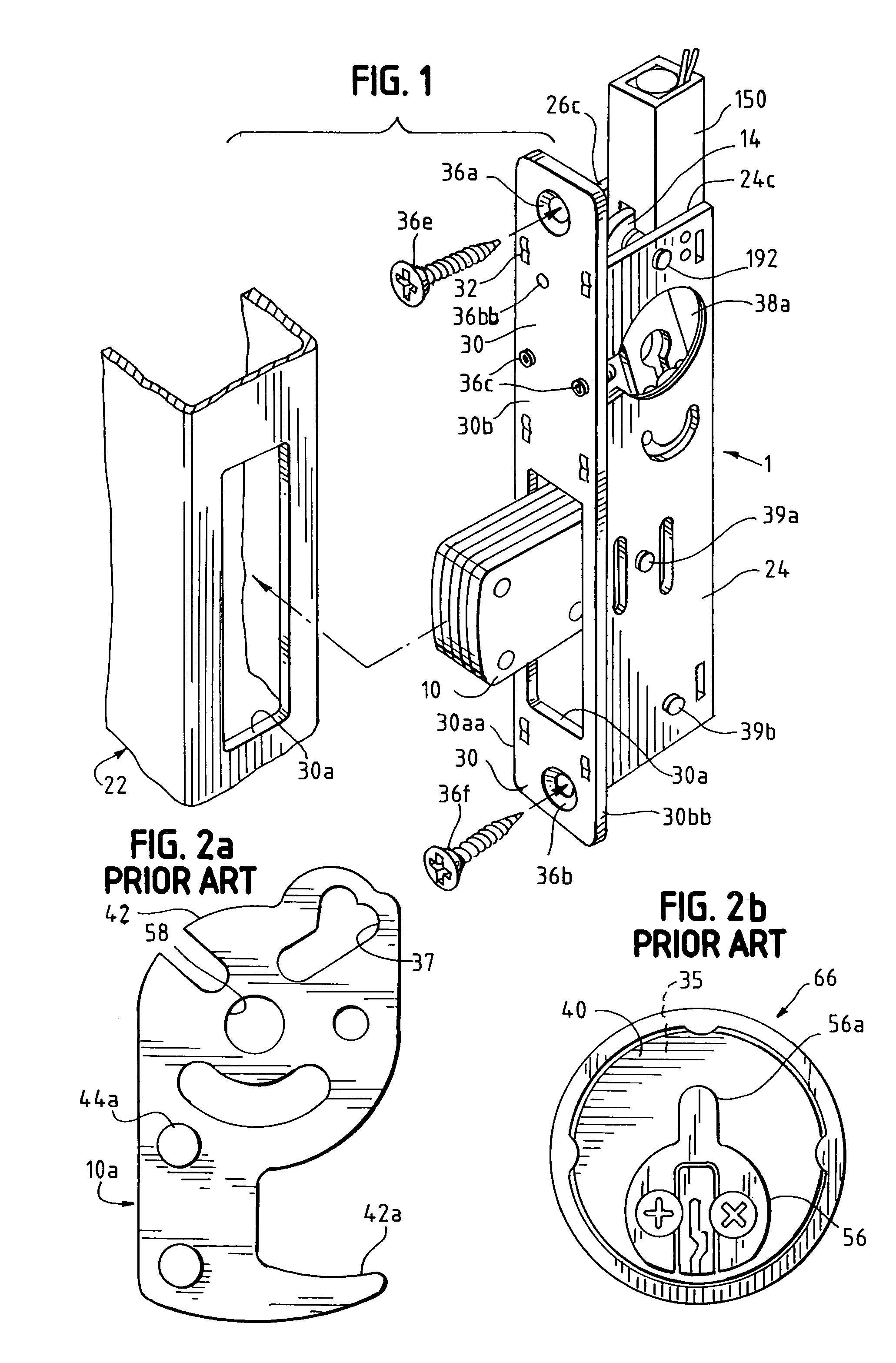
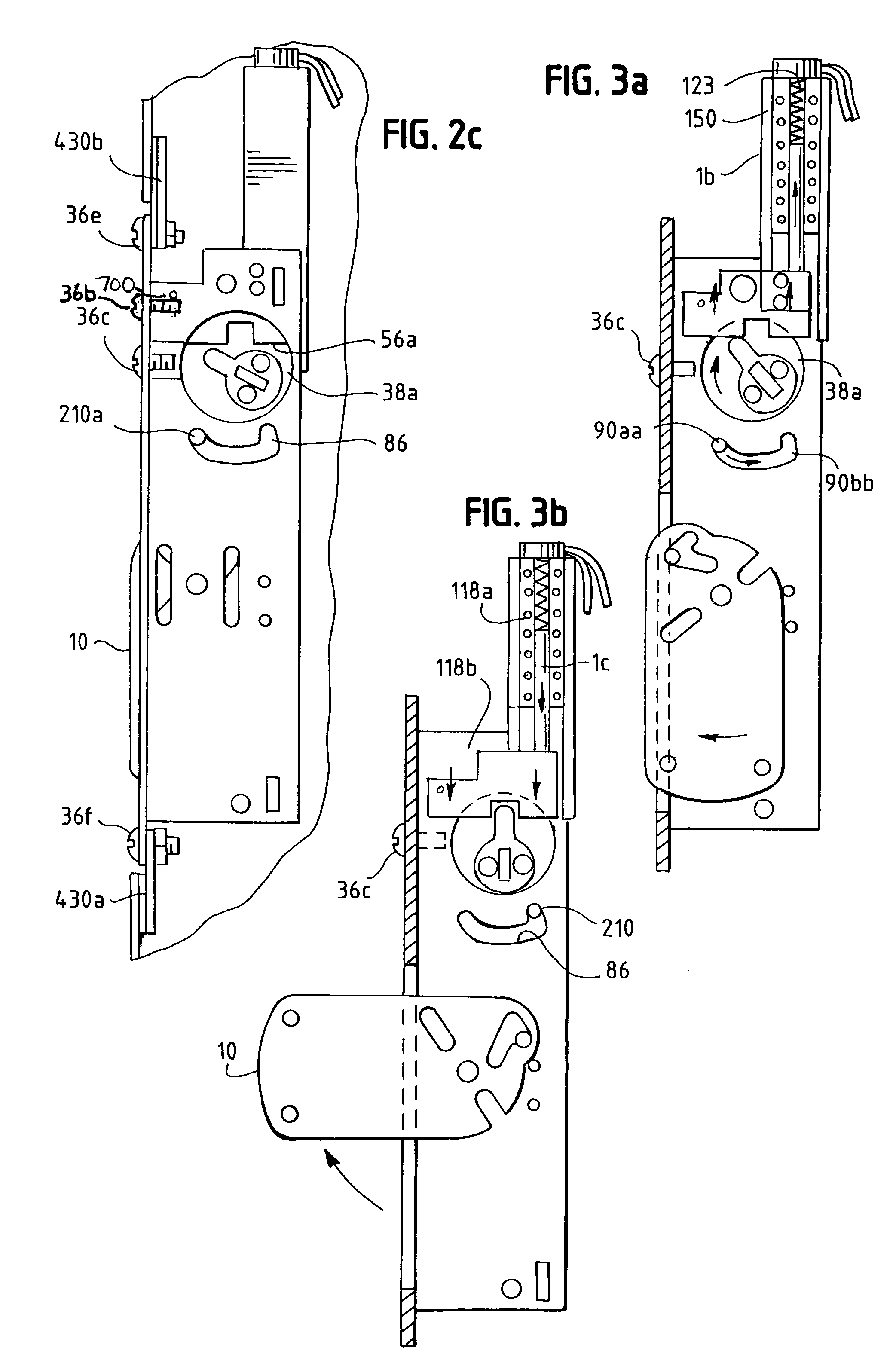
[0069]My electromagnetic integrated lock 1 comprises electromagnetic lock components with integrated prior art dead bolts 10 or hook bolts 10a. Each deadbolt 10 or hook bolt 10a was previously installed within a predetermined metal hollow doorframe casing 22 which comprises a door. The great advantage of my integrated lock is enhanced security without undue destruction of the existing hollow metal doorframe casing 22 and previously installed mechanical lock components.

[0070]My integrative lock components fit within any hollow metal doorframe casing 22, but most preferably within a narrow stile glass core / aluminum doorframe casing. Other door frames with similar material, mechanical and other physical properties are also within the scope of my invention. Also included within my invention are integrated lock components for other securing and secured structures, such as safe deposit boxes or safes. These other secured structures must comprise the necessary space and wiring ...


PUM


Abstract

Described herein is a locking device and method which integrates mechanical components in a hollow metal door frame with electronic access components. The electronic components override the original mechanical components of the lock to create a fail-safe situation in which the original mechanical lock may be disabled. In the preferred embodiment, my upgraded locking device can be re-installed within a hollow door frame, thereby minimizing service costs and doorframe modification costs. The electronically controlled component can be a cam retaining locking bar which contains a roll pin and an open area bordered by two cut sides. The open space eases lock installation with a door by avoiding protruding door structures such as metal tabs.

Description

[0001]This application is a continuation in part of U.S. patent application Ser. No. 10 / 787,723 filed Feb. 26, 2004, now U.S. Pat. No. 7,296,448.BACKGROUND OF THE INVENTION[0002]My invention relates to the structure and operation of a previously installed mechanical door lock which is upgraded with override electromagnetic lock components. In particular my invention relates to electromagnetic locking components and deadbolt (or hook bolt), all of which are enclosed within a hollow doorframe casing. However, my new lock is also adaptable to other doors or other closed containers or spaces which require a fail-secure electronic locking component which overrides previously installed mechanical locking components.[0003]In the preferred embodiment, my integrated lock is best suited to narrow stile doors, such as doors generally comprised of a glass core with a surrounding hollow metal frame. The lateral longitudinal plate comprises a longitudinal surface from which the bar or bolt extend...

Claims


Application Information

Patent Timeline
IPC IPC(8): E05B47/06E05B47/00E05B49/00E05C1/06
CPCE05B9/08E05B47/0002E05B47/023E05B47/0004E05B63/0013E05B2047/0086E05B2047/0094G07C9/00896Y10T70/7062Y10T70/7102Y10T70/7107Y10T70/713Y10T292/1021
Inventor SHAW, BARRY M.
Owner SHAW BARRY M
Why Eureka
Try Eureka