Lens device and lens barrel

a lens device and lens barrel technology, applied in the field of lenses barrels, can solve the problems of deteriorating lens performance, unable to adapt to changes in environmental conditions, and high expansion coefficient of glass lens elements

Inactive Publication Date: 2008-12-30
FUJI PHOTO OPTICAL CO LTD
View PDF7 Cites 13 Cited by
  • Summary
  • Abstract
  • Description
  • Claims
  • Application Information

AI Technical Summary

Benefits of technology

[0007]It is therefore an object of the present invention to prevention a lens device and a lens barrel which keeps an optical lens element held in the lens barrel in desired optical performance even when the optical lens element encounters a diametrical change due to environmental variations.

Problems solved by technology

The problem encountered by such a plastic lens element is a higher expansion coefficient than glass lens elements and hardly adaptable to changes in environmental conditions such as ambient temperature and / or humidity.
In consequence, the plastic lens element causes deterioration in lens performance resulting from a deviation of optical axis due to thermal expansion.
However, the optical lens element with a circumferential rim structure and the lens barrel to fit in the circumferential rim structure are not versatile in configuration and remain costly alternatives.
However, it goes counter to cost saving of the lens barrel, and besides leading to an increase in coaxial misalignment between the optical lens element and the lens barrel, to form the lens barrel so as to provide a clearance around a periphery of the optical lens element.

Method used


Image

  • Lens device and lens barrel
  • Lens device and lens barrel
  • Lens device and lens barrel

Examples


Embodiment Construction

[0015]In the following description, parts or mechanisms of a projector which are not direct importance to the invention and parts or mechanisms of a projector which are purely of conventional construction will not be described in detail since their construction and operation can be easily be arrived at by those skilled in the art.

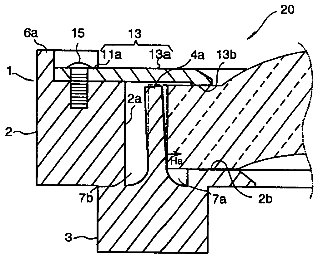
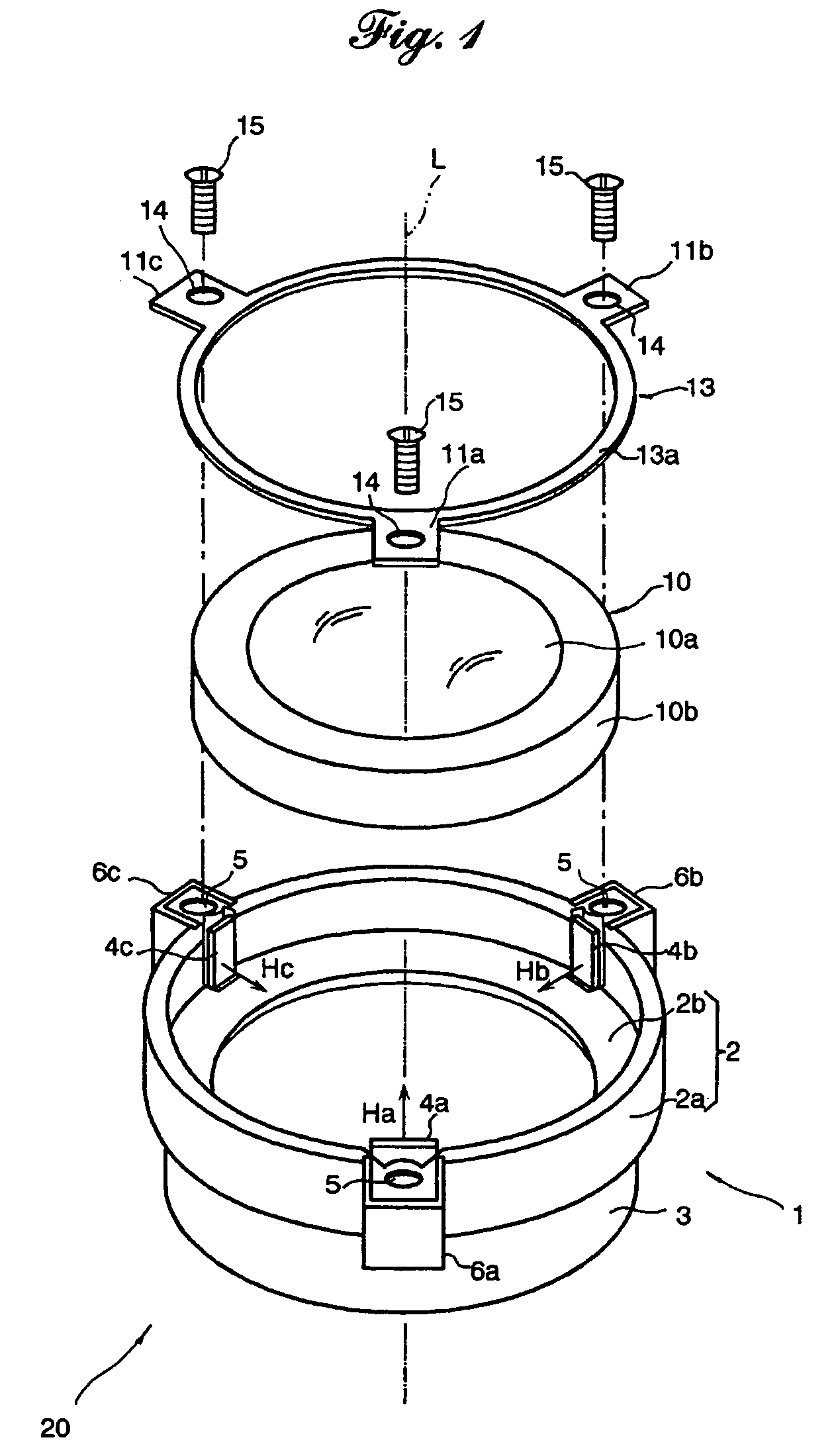
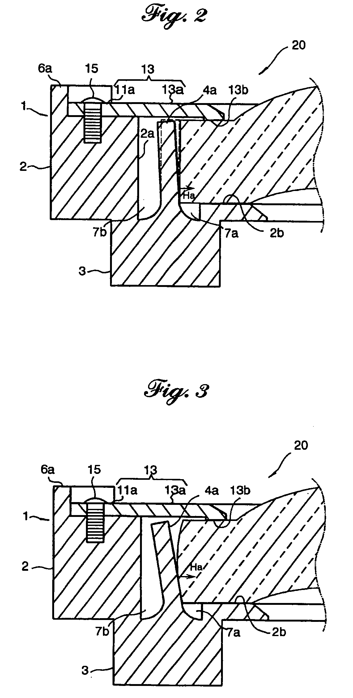
[0016]Referring to the accompanying drawings in detail, and in particular, to FIGS. 1 and 2 showing a lens device 20 according to an embodiment of the present invention, the lens device 20 comprises a lens barrel 1, an optical lens element 10 and a retainer ring 13. The optical lens element 10 comprises a convex lens portion 10a and a cylindrical flange portion 10b which are formed as an integral plastic element by injection molding. The lens barrel 1 for receiving and holding the optical lens element 10 is formed as an integral plastic member by injection molding. The lens barrel 1 comprises a lens holding barrel portion 2 formed by a coupled wall 2a and a...


PUM


Abstract

A lens device includes elastic bracing struts arranged at regular intervals which are deformed by a lens element supported in a lens barrel so as thereby to hold down a periphery of the lens element in directions perpendicular to an optical axis of the lens element with elastic force when the lens element causes a diametrical change due to environmental variations, so that the lens element is prevented from being brought into misalignment, and besides retaining its optical performance.

Description

BACKGROUND OF THE INVENTION[0001]1. Field of the Invention[0002]The present invention relates to a lens barrel for holding an optical lens element and a lens device comprising an optical lens element and a lens barrel.[0003]2. Description of Related Art[0004]In recent years because of a strong demand for a high optical performance and a decreased number of lens elements of a lens system for a liquid crystal projector, it is predominant to employ aspherical plastic lens elements. The problem encountered by such a plastic lens element is a higher expansion coefficient than glass lens elements and hardly adaptable to changes in environmental conditions such as ambient temperature and / or humidity. In consequence, the plastic lens element causes deterioration in lens performance resulting from a deviation of optical axis due to thermal expansion.[0005]Japanese Unexamined Patent Publication No. 2000-187144 describes one of lens device structures for preventing a plastic lens and a lens ba...

Claims


Application Information

Patent Timeline
Patent Type & Authority Patents(United States)
IPC IPC(8): G02B7/02
CPCG02B7/02
Inventor KURODA, YASUTO
Owner FUJI PHOTO OPTICAL CO LTD
Why Eureka
Try Eureka