System and method for monitoring link delays and faults in an IP network

a technology of internet protocol and link delay, applied in the field of computer network management, to achieve the effect of reducing monitoring overhead (cost)

Inactive Publication Date: 2008-12-30
ALCATEL-LUCENT USA INC
View PDF6 Cites 10 Cited by
  • Summary
  • Abstract
  • Description
  • Claims
  • Application Information

AI Technical Summary

Benefits of technology

[0012]Disclosed and claimed herein is a novel two-phased technique for fully and efficiently monitoring link latencies and faults in an ISP or Enterprise IP network, using path-oriented tools. Some embodiments of the technique are failure-resilient, and ensure complete coverage of measurements by selecting monitoring stations such that each network link is always in the routing tree of some station. The technique also reduces the monitoring overhead (cost), which consists of two cost components: (1) the infrastructure and maintenance costs associated with monitoring stations and (2) the additional network traffic due to probe messages. Minimizing the latter is especially important when information is collected frequently (e.g., every 15 minutes) to monitor continually the state and evolution of the network.

Problems solved by technology

The problem of computing the minimal set of stations whose routing trees cover all network links is NP-hard.

Method used


Image

  • System and method for monitoring link delays and faults in an IP network
  • System and method for monitoring link delays and faults in an IP network
  • System and method for monitoring link delays and faults in an IP network

Examples


example 1

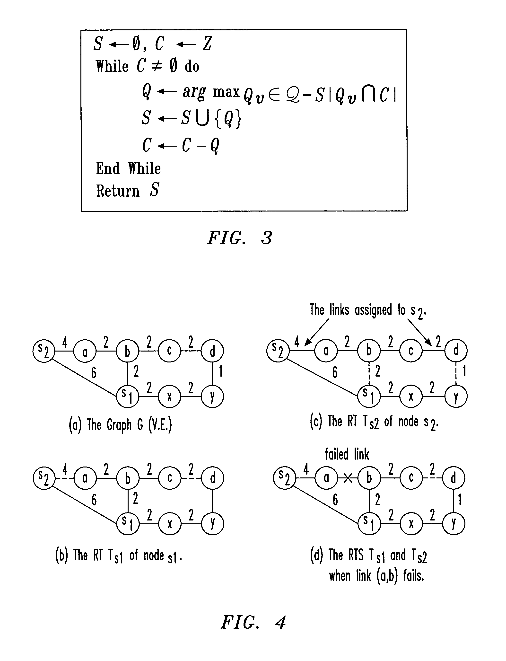
[0065]Consider the graph G(V,E) depicted in FIG. 4A, where each link is labeled with its weight.

[0066]Let S={s1,s2} be the set of selected monitoring stations. The RTs Ts1 and Ts2 are the shortest path trees rooted at nodes s1 and s2 as illustrated in FIGS. 4B and 4C, respectively. The simple probe message assignment algorithm assigns all graph links to be monitored by s1 except the links (s2,a) and (c,d) which are monitored by s2. Note that s2 transmits two probe messages m(s2,c) and m(s2,d) that traverse nodes a, b and c to measure the latency of link (c,d). Now, consider the failure of link (a,b) that causes the RTs of s1 and s2 to be modified as shown in FIG. 4D. (RTs typically adapt to failures in a few seconds or a few tens of seconds, depending on IP routing protocol parameter settings.) Specifically, the new RT for s1 contains the link (s2,a) instead of (a,b), while the tree for s2 contains the links (s1,b) and (y,d) instead of (a,b) and (c,d). Clearly, neither s1 nor s2 det...

example 2

[0072]Consider the graph in Example 1, and assume a failure of the link (a,b) monitored by s1. The hop distances from s1 to nodes a, b before the failure are hs1,b=1 and hs1,a=2, and they remain the same after (a,b) fails. Thus, s1 cannot detect the failure of link (a,b).

[0073]The above problem can be fixed by associating the same destination address with the two probe messages for link e=(u,v). Let m(s,t,h) denote the probe message sent by source s to a destination node t with TTL value set to h. Further, let Rm(s,t,h) be the node that replies to the probe message. Assuming that node u is closer to station s than node v, i.e., hs,us,v, station s can monitor both the delay as well as failure of link e by sending the following two probe messages: m(s,v,hs,u) and m(s,v,hs,v). These messages have the same destination, v, but they are sent by s with different TTL values.

[0074]Clearly, in the absence of failures, the reply for the first message is sent by node u while the reply for the s...

example 3

[0078]Consider the graph in Example 1 where station s2 monitors links (s2,a) and (c,d), and s1 monitors the remaining links. Suppose that for probe message m(s2,d,3) that monitors link (c,d), Rm(s2,d,3) is y instead of c. This could be the result of the failure of either link (c,d) or (a,b). In both cases, the new routing path from s2 to d traverses nodes s1, x and y. Since s2 does not monitor link (a,b), it cannot conclude, by itself, which of links (a,b) or (c,d) have failed.

[0079]An algorithm for accurately pinpointing the faulty link, in which each monitoring station sends its failure information to the NOC, will now be presented.

[0080]As shown in Example 3, with probe message assignment , when a link fails, the station monitoring the link detects the failure, but may not always be able to accurately identify the location of the failed link. However, station s can narrow down the possible candidates to links in the path connecting it to the failed link.

[0081]It will be stated wi...


PUM


Abstract

A system for, and method of, monitoring link delays and faults in an IP network. In one embodiment, the system includes: (1) a monitoring station identifier that computes a set of monitoring stations that covers links in at least a portion of the network and (2) a probe message identifier, coupled to the monitoring station identifier, that computes a set of probe messages to be transmitted by at least ones of the set of monitoring stations such that the delays and faults can be determined.

Description

TECHNICAL FIELD OF THE INVENTION[0001]The present invention is directed, in general, to computer network management and, more specifically, to a system and method for monitoring link delays and faults in an Internet Protocol (IP) network.BACKGROUND OF THE INVENTION[0002]The demand for sophisticated tools for monitoring network utilization and performance has been growing rapidly as Internet Service Providers (ISPs) offer their customers more services that require quality of service (QoS) guarantees and as ISP networks become increasingly complex. Tools for monitoring link delays and faults in an IP network are critical for numerous important network management tasks, including providing QoS guarantees to end applications (e.g., voice over IP), traffic engineering, ensuring service level agreement (SLA) compliance, fault and congestion detection, performance debugging, network operations and dynamic replica selection on the Web. Consequently, a recent flurry of both research and indu...

Claims


Application Information

Patent Timeline
Patent Type & Authority Patents(United States)
IPC IPC(8): G06F11/00H04L12/24H04L12/26
CPCH04L41/0677H04L43/0852H04L41/0213H04L41/5003H04L41/5009H04L41/5045H04L43/0888H04L43/10H04L43/12
Inventor BEJERANO, YIGALRASTOGI, RAJEEV
Owner ALCATEL-LUCENT USA INC
Why Eureka
Try Eureka