Disk-storing disk device having a drive unit and a transporting-unit supported about fulcrum

a technology of disk storage and drive unit, which is applied in the direction of recording head arrangement, data recording, instruments, etc., can solve the problems of preventing miniaturization, reducing the depth size of the case, and increasing the difficulty of miniaturizing the case, so as to prevent rattling and reduce the depth of the case.

Active Publication Date: 2008-12-30
ALPINE ELECTRONICS INC
View PDF12 Cites 5 Cited by
  • Summary
  • Abstract
  • Description
  • Claims
  • Application Information

AI Technical Summary

Benefits of technology

[0012]Accordingly, the present invention has been made for solving the conventional problems described above, and it is an object thereof to provide a disk-storing disk device capable of setting a small depth size of a casing as well as being capable of securely conveying a disk inserted through an insertion opening toward a holder.
[0016]The transporting unit is rotated inside the casing about the first fulcrum positioned on the first side, so that the arrangement region of the holders is arranged disproportionately on the first side. Therefore, the disk clamped between the transfer roller and the clamp member is conveyed while approaching the holder along with the rotation of the transporting unit, so that the disk can be securely transferred to the holder.
[0019]In such a manner, when the rotating regions of the drive unit and the transporting unit are configured so as to overlap with each other, the drive unit can be located at a position close to the front face of the casing, further reducing the depth size of the casing.
[0026]By providing the intermediate portion as described above, when the transporting unit is located at the transfer operation position, the contact length between the transfer roller and the disk is short. Hence, when the transporting unit is rotated to the standby position, the transfer roller is directly separated from the disk. Also, since the disk can be clamped between the transfer roller and the clamp member at the time when the disk is inserted into the insertion opening to some extent, the disk can be securely conveyed into the casing, improving operability during inserting the disk.
[0028]In the above structure, when the disk device is under transportation and storage conditions, by retaining the drive unit to the transporting unit, the drive unit and the transporting unit can be prevented from rattling.
[0029]According to the present invention, by efficiently arranging respective units within the casing, the depth size of the casing can be reduced. Also, to the holders positioned disproportionately on the first side about the insertion center line of the disk, the disk inserted through the insertion opening can be securely conveyed.

Problems solved by technology

However, in the conventional disk device described above, since the withdrawn position of the drive unit is located between the front surface of the case and the tray installation region, there is limitation in reducing the depth size of the case, preventing miniaturization.
However, since the transfer roller and the clamping member are moved in a direction perpendicular to the axial direction of the transfer roller, a large movement region is necessary therefor, so that miniaturizing the case becomes more difficult.

Method used


Image

  • Disk-storing disk device having a drive unit and a transporting-unit supported about fulcrum
  • Disk-storing disk device having a drive unit and a transporting-unit supported about fulcrum
  • Disk-storing disk device having a drive unit and a transporting-unit supported about fulcrum

Examples


Embodiment Construction

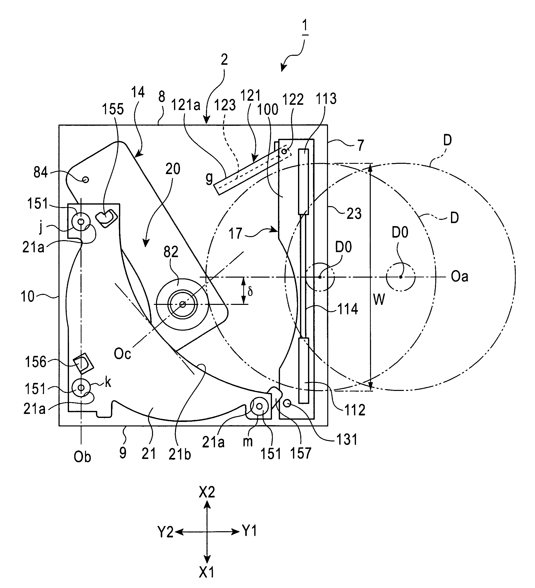
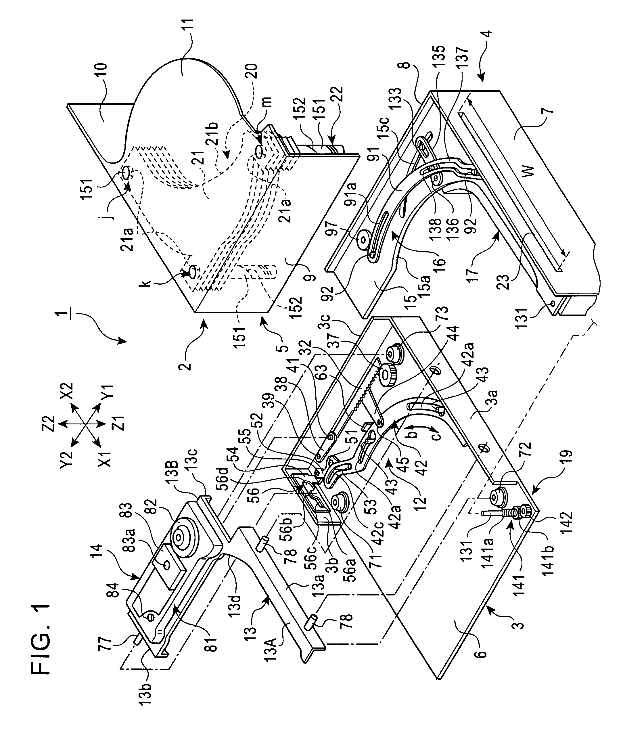
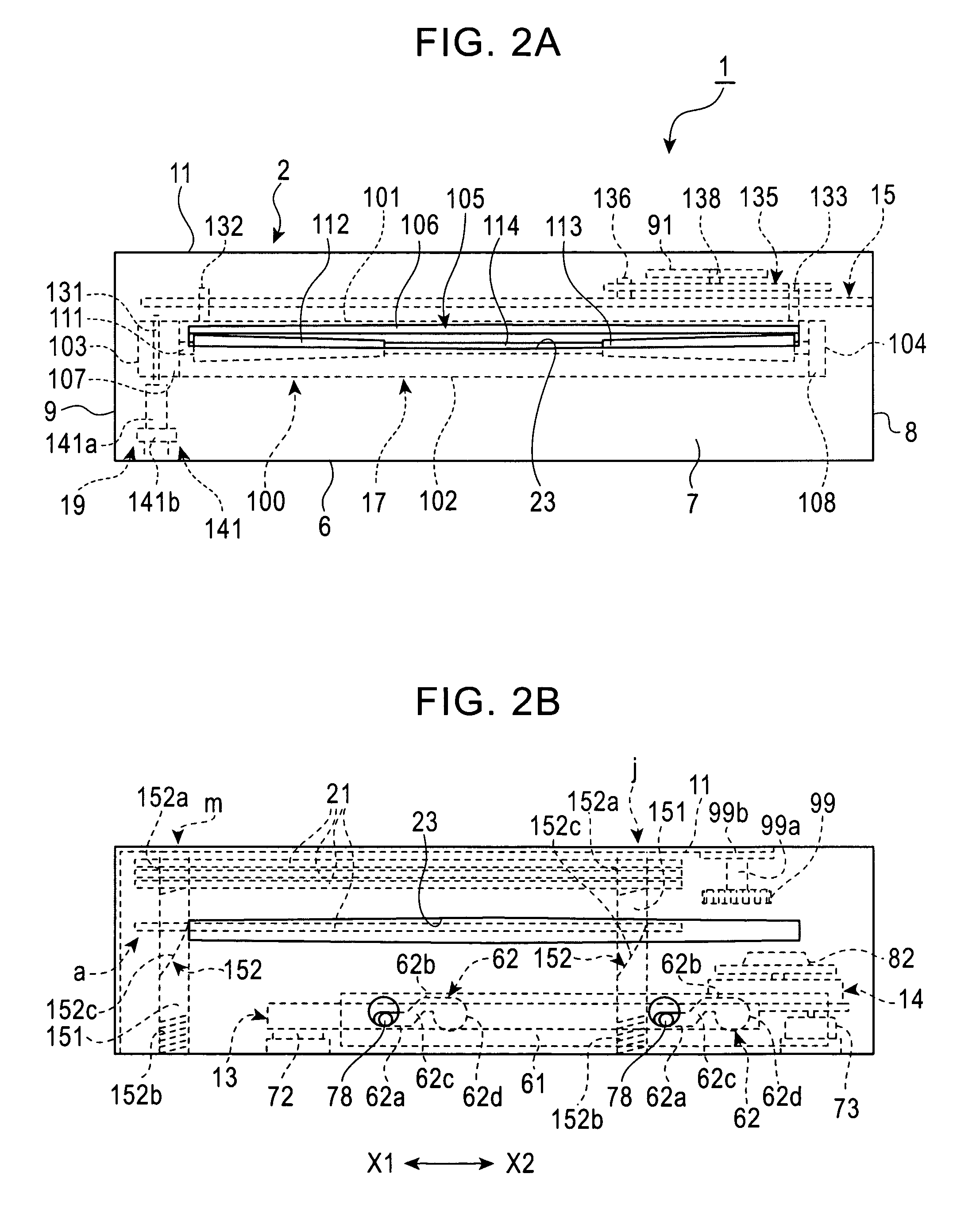
[0046]FIG. 1 is an exploded perspective view of the entire structure of a disk-storing disk device according to an embodiment of the present invention. FIGS. 2A and 2B are front views of a casing of the disk-storing disk device viewed from the front; FIG. 2A mainly shows a transporting unit within the casing; and FIG. 2B mainly shows a holder, holder selecting means, and a drive unit. FIGS. 3 to 5 are plan views of the structure of a first power transfer unit arranged on the bottom of the casing showing it's every operation; FIGS. 6 and 7 are plan views of the drive unit and the support base showing their every operation; and FIGS. 8A and 8B show a restriction state and a restriction-released state of the support base of the drive unit, in which FIG. 8A is a side view of FIG. 6 viewed in arrow direction VIII, and FIG. 8B is a side view of FIG. 7 viewed in arrow direction VIII; FIGS. 9 to 10 are plan views of the structure of a second power transfer unit showing it's every operation;...


PUM

PropertyMeasurementUnit
sizeaaaaaaaaaa
revolution speedaaaaaaaaaa
diameteraaaaaaaaaa

Abstract

In a disk-storing disk device according to the present invention, within a casing having an insertion opening formed on the front face for inserting a disk, a plurality of holders are arranged in piles disproportionately on the X1 side about an insertion center line while a drive unit is rotatably supported on the X2 side from the insertion center line. When any of the holders is selected and a disk is inserted through the insertion opening, the disk is clamped to transfer rollers. A transporting unit is counterclockwise rotated while the disk is transferred with the transfer rollers. By the rotation, the disk is securely conveyed to the holder arranged disproportionately on the X1 side. Thereby, efficiency of arranging respective units in the casing is improved so as to provide a disk-storing disk device with short depth size.

Description

CROSS-REFERENCE TO RELATED APPLICATION[0001]This application is related to co-pending non-provisional application Ser. No. 11 / 386,079, filed on Mar. 21, 2006, entitled DISK DEVICE.BACKGROUND OF THE INVENTION[0002]1. Field of the Invention[0003]The present invention relates to a disk-storing disk device in that one disk is selected from a plurality of disks stored in a casing for driving it.[0004]2. Description of the Related Art[0005]An in-dash type on-vehicle disk-storing disk device includes a case complying with 1 DIN or 2 DIN standards in size, and a disk is inserted into the case one by one so as to store a plurality of disks in the case. Disk selecting means is provided in the case, and a space between the selected disk and a disk adjacent thereto is increased by the disk selecting means so that a drive unit moves into the space so as to clamp the selected disk for driving it.[0006]In disk devices disclosed in Japanese Unexamined Patent Application Publication No. 2003-217223 ...

Claims


Application Information

Patent Timeline
Patent Type & Authority Patents(United States)
IPC IPC(8): G11B17/04
CPCG11B17/021G11B17/223
Inventor TATEKAWA, TSUTOMUSUZUKI, SHOJISUZUKI, TOKIO
Owner ALPINE ELECTRONICS INC
Why Eureka
Try Eureka