Multilayer image display device

a multi-layer image and display device technology, applied in the direction of picture reproducers using projection devices, static indicating devices, instruments, etc., can solve the problems of unnecessarily increasing the setting environment, not fully utilizing the advantages of a full graphic-type display, etc., to achieve the effect of suppressing external light influence on a multi-layer display image, compact device body, and suppressing image projection devices

Active Publication Date: 2018-12-04
ALPINE ELECTRONICS INC
View PDF17 Cites 1 Cited by
  • Summary
  • Abstract
  • Description
  • Claims
  • Application Information

AI Technical Summary

Benefits of technology

[0010]An object of the present disclosure is to provide a multilayer image display device capable of down-sizing and improved visibility.
[0012]According to the this configuration, instead of a conventional inclined disposed half mirror, multilayer image display is performed by superimposing a real image including i) an image projected by an image projection device on ii) an image which is displayed on the image display device and transmits through a transparent screen. The transparent screen includes an anisotropic optical film which reflects light incident at a predetermined angle with directivity, and transmits light incident at an angle other than the predetermined incident angle. Therefore, a depth size of the device can be reduced, and it is not necessary to increase a luminance of the image of the image display device, which transmits through the transparent screen. Further, a real image can be visually recognized, and therefore a multilayer image display device having high visibility can be provided.
[0018]According to the this configuration, the converging angle can be adjusted at an angle with a high converging efficiency, and insufficiency of a luminance of a reflected image can be efficiently solved. A converging light angle adjustment unit, for example, may comprise a mechanical mechanism to move a specific direction converging light source and an optical mechanism (such as lens) to change a converging angle.
[0020]According to the this configuration, which is different from the case where a transparent OLED is used, cost may be suppressed by using an LCD panel.
[0022]According to the this configuration, reflection of a light incident from outside of the image display device and the image projection device can be suppressed. Therefore, external light influence on a multilayer display image can be suppressed.

Problems solved by technology

However, in such a setting, advantages of a full graphic-type display are not fully utilized.
However, it is not useful to unnecessarily increase setting environments (e.g., the size) of a cluster panel from original setting environments where “a visor for external light reflection is needed”, and “a steering wheel is provided on a front side”.
However, such a display becomes more expensive than an LCD that is currently inexpensively supplied.
In this manner, the half mirror 102 two-layer method has many restrictions, including for example, difficulty in downsizing the display device.
Therefore, keeping a high transmittance is not easy.
Furthermore, wiring makes display impossible at least on three sides.
According to this configuration, a totally reflected luminous flux in a projection image by an image projection display device on a transparent screen may be limited such that a luminance of the reflected image may be insufficient.

Method used


Image

  • Multilayer image display device
  • Multilayer image display device
  • Multilayer image display device

Examples


Embodiment Construction

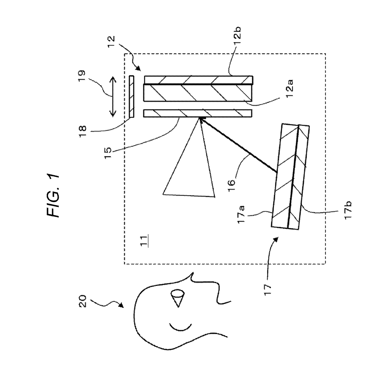
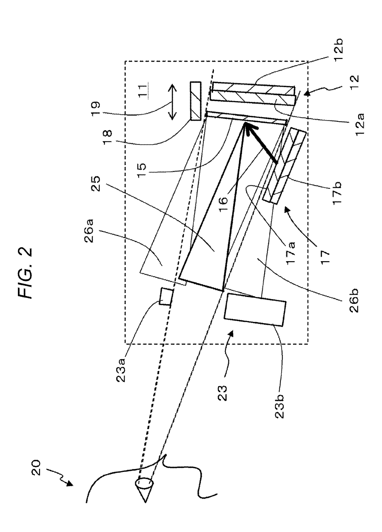
[0029]An embodiment of the present disclosure will be described with reference to drawings. FIG. 1 is an outline explanatory view of a configuration of a two-layer image display device 11 which is a multilayer image display device according to the embodiment of the present disclosure.

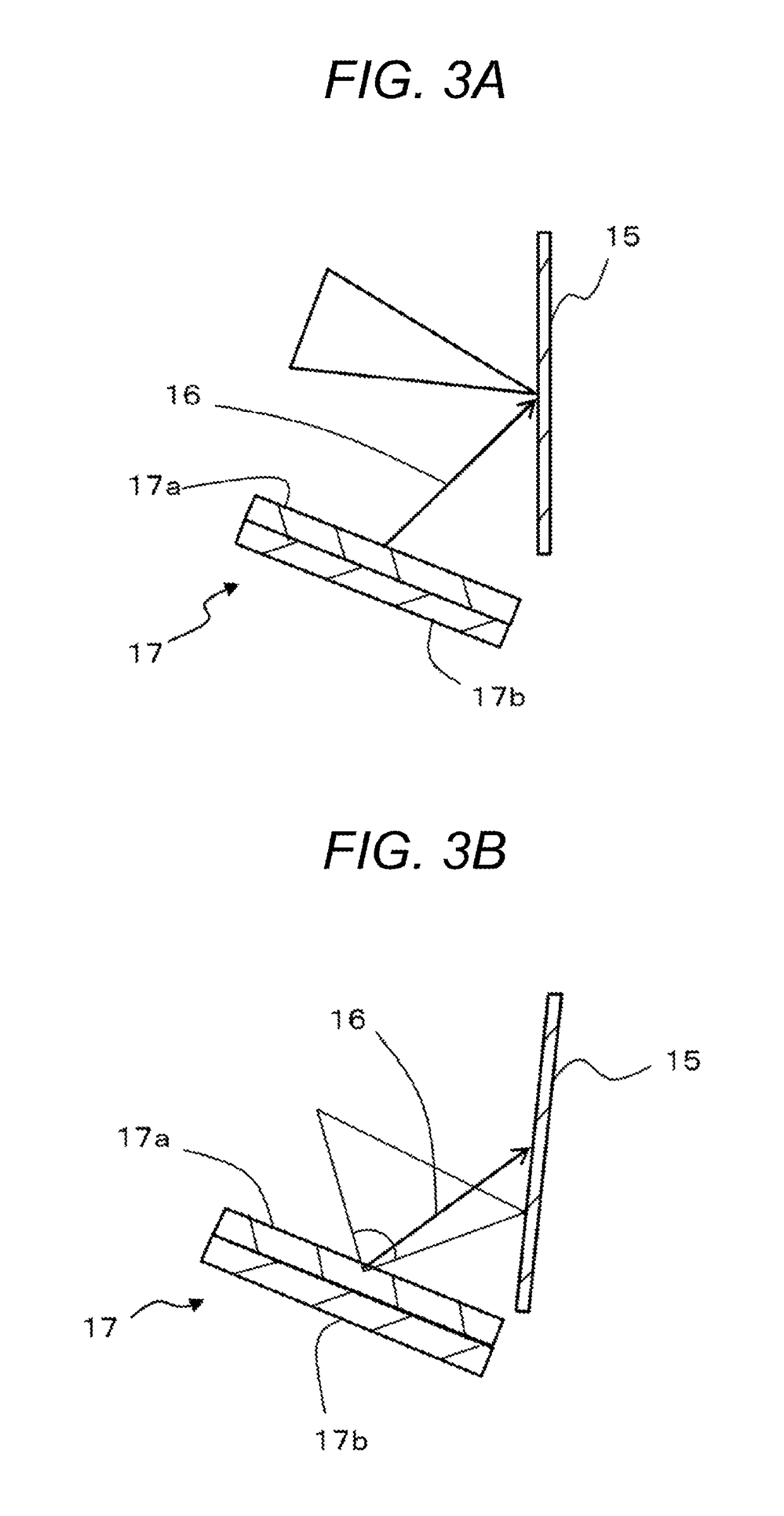
[0030]In FIG. 1, the two-layer image display device 11 includes a back side liquid crystal display (LCD) 12, a transparent screen 15, a lower side LCD 17, and a visor 18. The back side LCD 12 is an image display device. The transparent screen 15 includes an anisotropic optical film and is disposed on a front side of a display screen 12a of the back side LCD 12. The lower side LCD 17 is an image projection device and disposed at a position opposite to the back side LCD 12 across from the transparent screen 15, and on a lower side of the transparent screen 15. The visor 18 is disposed on an upper side of the back side LCD 12 and the transparent screen 15, and extends in a depth direction 19 (lateral direc...


PUM

PropertyMeasurementUnit
transmittanceaaaaaaaaaa
transmittance ratioaaaaaaaaaa

Abstract

A two-layer image display device includes a back side LCD, a transparent screen, and a lower side LCD. The back side LCD displays an image on a display screen. The transparent screen is disposed on a front side of the display screen of an image display device. The lower side LCD projects an image from a lower position of the transparent screen. The transparent screen reflects, with directivity, light incident at a predetermined angle and includes an anisotropic optical film which transmits light incident at an angle other than the predetermined incident angle. The lower side LCD is disposed at a position where the image incident at the predetermined angle is projected and reflected on the transparent screen. The back side LCD is disposed at a position where incident light from an image displayed on the display screen transmits through the transparent screen.

Description

RELATED APPLICATION[0001]The present application claims priority to Japanese Patent Application Number 2016-099424, filed May 18, 2016, the entirety of which is hereby incorporated by reference.BACKGROUND[0002]1. Field[0003]The present disclosure relates to a multilayer image display device including an image display device, an image projection device, and a transparent screen.[0004]2. Description of the Related Art[0005]Improved image displays with a full graphic-type cluster panel (display) are increasingly used in vehicles. These full graphic-type cluster panels can display dynamic and various information types, as compared to a conventional meter cluster panel. When such dynamic displays are used, a driver may not always require or desire the meter display.[0006]In this case, contents of a meter is fixed to a standard specification and area, and only in an area with a high degree of freedom is a various display considered. However, in such a setting, advantages of a full graphic...

Claims


Application Information

Patent Timeline
Patent Type & Authority Patents(United States)
IPC IPC(8): G09G3/36G06F3/147H04N9/31B60K35/00G02F1/13357
CPCG06F3/147B60K35/00G09G3/36H04N9/315H04N9/317G02F1/1336B60K2350/2039B60K2350/2052B60K2350/2082B60K37/02B60K2370/23B60K2370/27B60K2370/31B60K2370/334G09G3/003G09G2300/023G09G2320/028G09G2320/068G09G2380/10
Inventor IMANISHI, SHUNICHI
Owner ALPINE ELECTRONICS INC
Why Eureka
Try Eureka