Birdcage resonator with coupling rings in addition to the ferrules

a technology of coupling rings and birds' cages, applied in the field of birds' cage resonators, can solve the problems of ferrule oscillation currents in the ferrules, bird cage resonators, and ferrule modes

Inactive Publication Date: 2009-01-13
SIEMENS HEALTHCARE GMBH
View PDF9 Cites 15 Cited by
  • Summary
  • Abstract
  • Description
  • Claims
  • Application Information

AI Technical Summary

Problems solved by technology

One of the disadvantages of birdcage resonators is what is known as ferrule modes, meaning currents that oscillate in the ferrules.
In the prior art the ferrule modes are disadvantageous since, in individual cases, they can be disruptive for the magnetic resonance imaging.
This is not always possible, however.

Method used


Image

  • Birdcage resonator with coupling rings in addition to the ferrules
  • Birdcage resonator with coupling rings in addition to the ferrules
  • Birdcage resonator with coupling rings in addition to the ferrules

Examples


Embodiment Construction

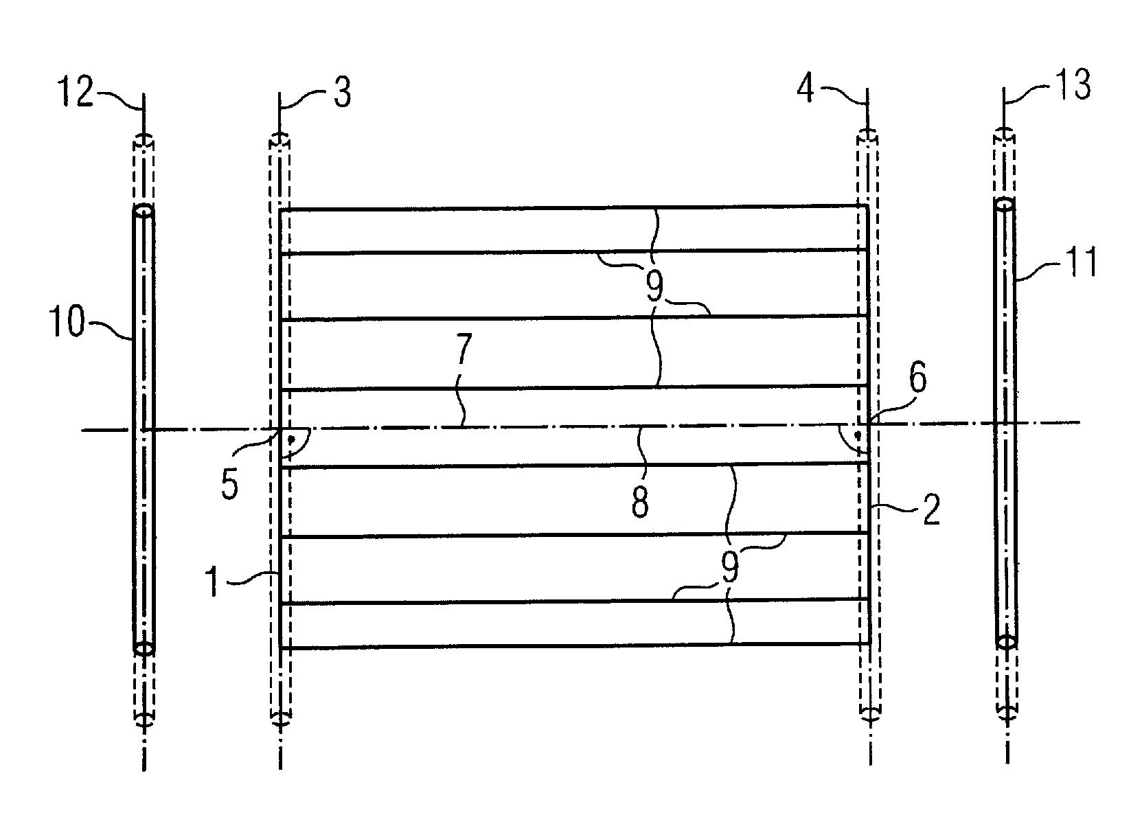
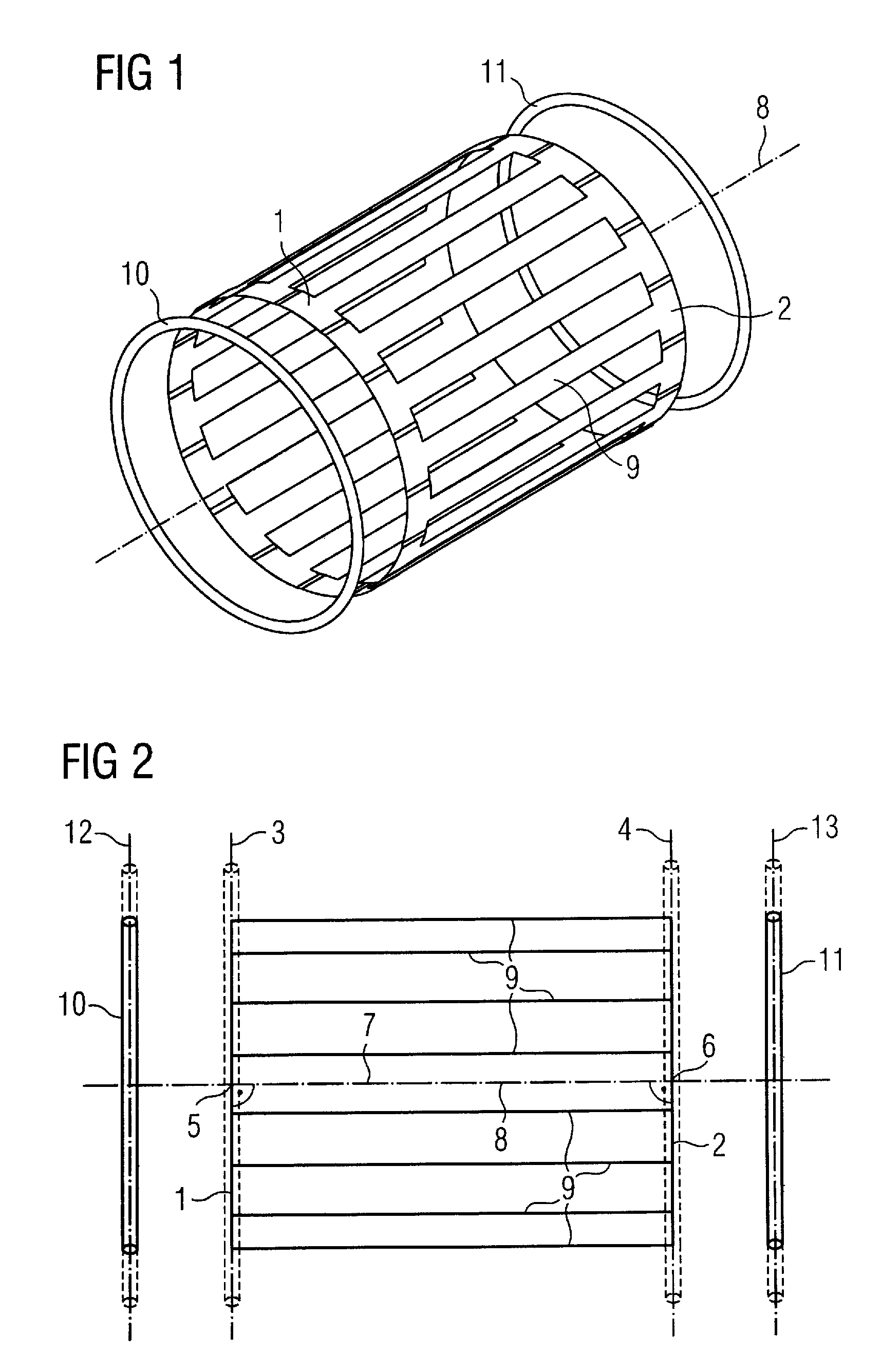
[0024]As shown in FIGS. 1 and 2, a birdcage resonator for magnetic resonance applications has a first ferrule 1 and a second ferrule 2. The ferrules 1, 2 are disposed in ferrule planes 3 and 4, respectively. The ferrule planes 3, 4 are parallel to one another. They exhibit a distance from one another, are thus spaced from one another.

[0025]The ferrules 1, 2 are normally of equal size. They can alternatively exhibit sizes different from one another. Furthermore, the ferrules 1, 2 are normally circular, but can alternatively exhibit a different shape, for example elliptical.

[0026]The ferrules 1, 2 exhibit ferrule centers 5, 6. The ferrule centers 5, 6 correspond to the center of gravity of the ferrules 1, 2. A connection line 7 of the ferrule centers 5, 6 with one another defines an antenna axis 8 of the birdcage resonator. The antenna axis 8 intersects the ferrules planes 3, 4 orthogonally.

[0027]The antenna axis 8 defines a cylindrical coordinate system. The terms “axial”, “radial” a...


PUM


Abstract

A birdcage resonator for magnetic resonance applications has two ferrules disposed in spaced-apart parallel ferrule planes. A line connecting the ferrule centers defines the antenna axis of the birdcage resonator, which orthogonally intersects the ferrule planes. The birdcage resonator has a number of antenna rods regularly distributed around the antenna axis, extending from ferrule to ferrule. The birdcage resonator has two coupling rings in addition to the ferrules that surround the antenna axis in respective coupling ring planes orthogonal to the antenna axis, and that are spaced from but coupling with the ferrules. The coupling rings are tuned to cause the ferrules to be resonant at frequencies other than without the coupling rings. The ferrules couple with one another in common eigenmodes, namely a common mode with a common mode frequency, and a push-pull mode with a push-pull frequency differing from the common mode frequency. The coupling rings are tuned such that the frequency of one of the eigenmodes does not correspond with any resonance frequency of the antenna rods. A feed device feeds electrical energy into the ferrules at the frequency of the eigenmode that corresponds with no resonance frequency of the antenna rods.

Description

BACKGROUND OF THE INVENTION[0001]1. Field of the Invention[0002]The present invention concerns a birdcage resonator for magnetic resonance applications.[0003]2. Description of the Prior Art[0004]Birdcage resonators for magnetic resonance apparatuses are generally known. They are normally constructed as follows.[0005]The birdcage resonator has a first ferrule and a second ferrule disposed in ferrule planes parallel to one another and spaced from one another. The ferrules exhibit ferrule centers. A connection line of the ferrule centers with one another defines an antenna axis of the birdcage resonator which orthogonally intersects the ferrule planes. The birdcage resonator furthermore has a number of antenna rods that are distributed regularly (normally uniformly) around the antenna axis. Each antenna rod extends from the first ferrule to the second ferrule.[0006]In magnetic resonance systems, birdcage resonators are used almost without exception as transmission antennas for excitati...

Claims


Application Information

Patent Timeline
Patent Type & Authority Patents(United States)
IPC IPC(8): G01V3/00
CPCG01R33/34046G01R33/34076
Inventor RENZ, WOLFGANG
Owner SIEMENS HEALTHCARE GMBH
Why Eureka
Try Eureka