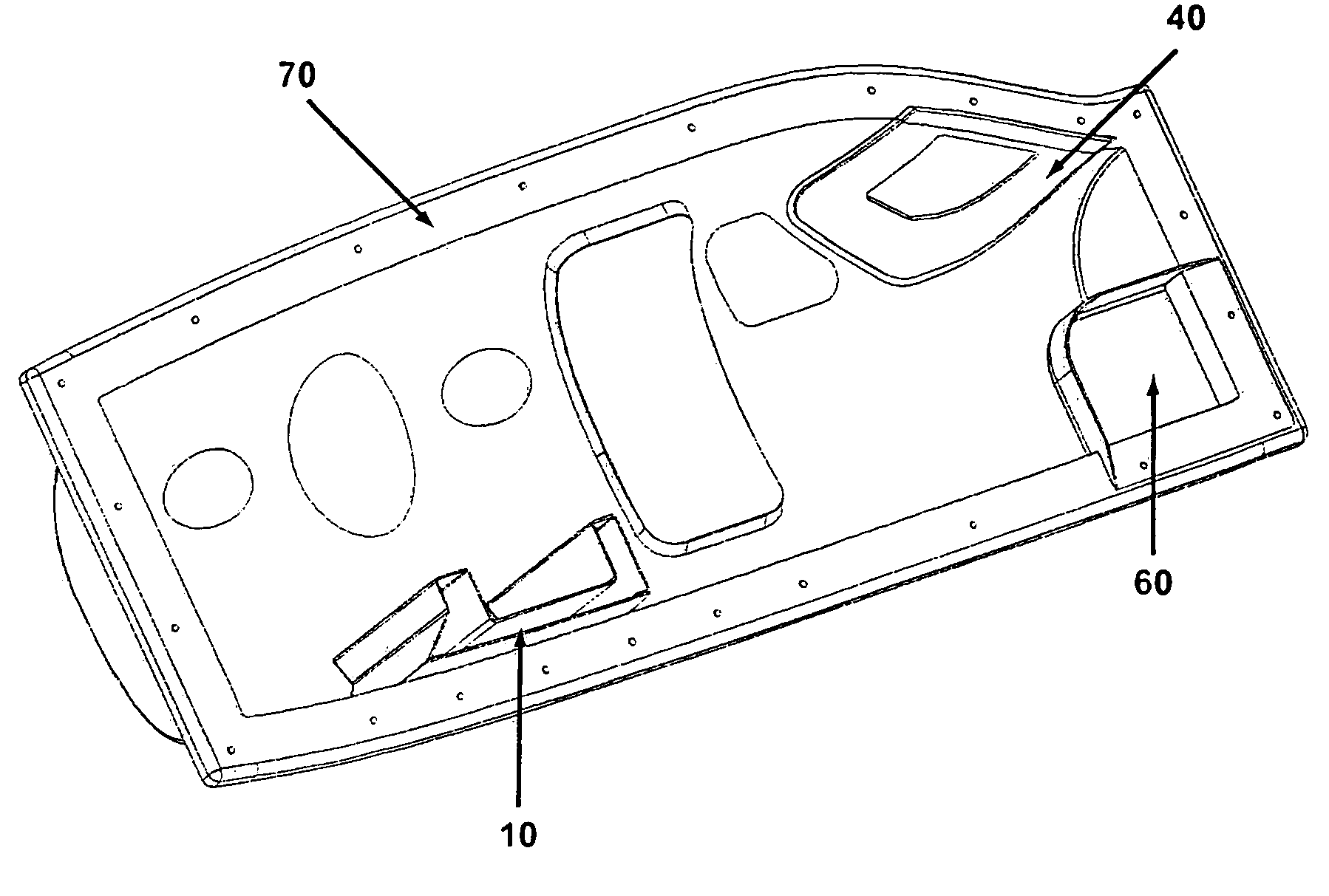
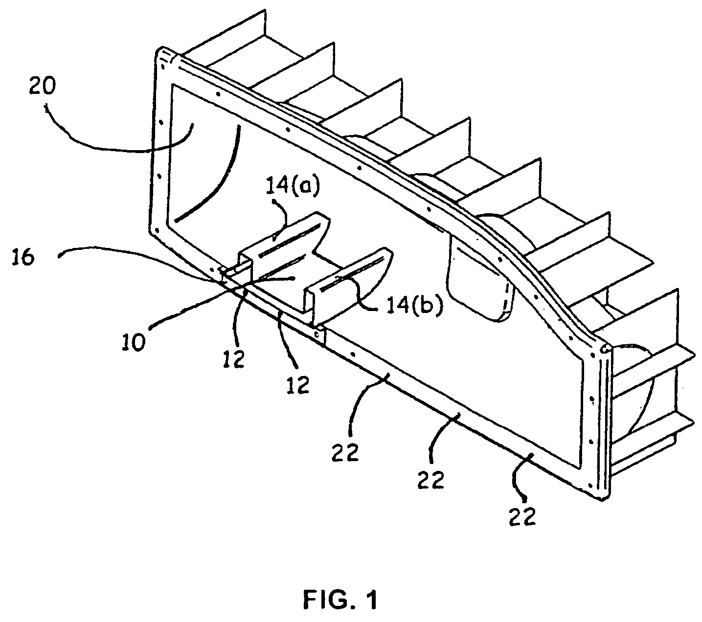
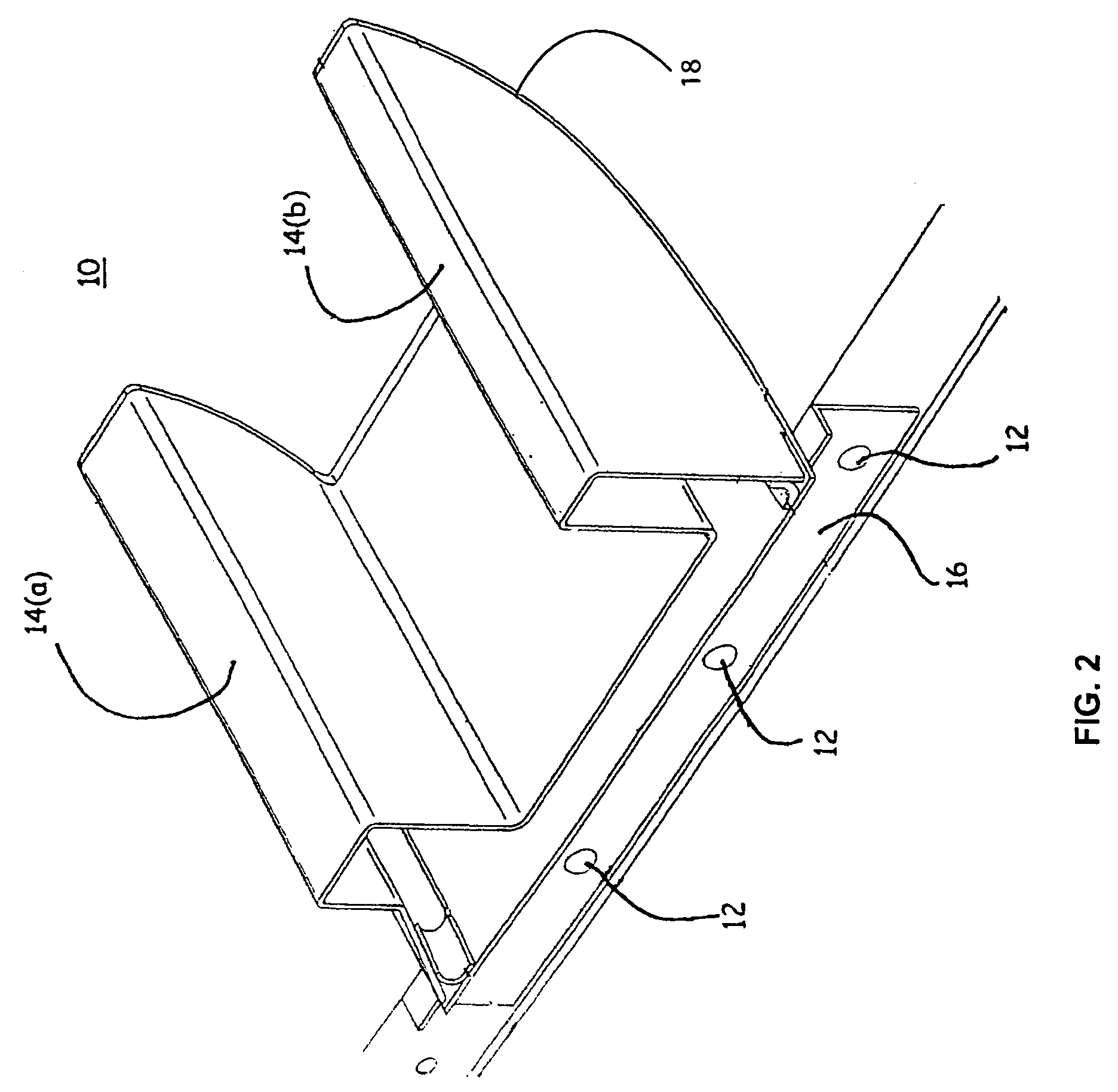
[0011]In one particularly innovative aspect, the present invention is directed to systems and methods for adjusting the location of the CG of an aircraft by shifting, or repositioning, the fuselage of an aircraft on its wing without requiring a complete retooling of the fuselage and wing assembly. The method preferably comprises providing a first mold of a portion of a fuselage of an aircraft; providing a second mold for a portion of a spar tunnel of said fuselage, said second mold being configured for adjustable mounting within said first mold; and detachably fixing said second mold at a desired location within said first mold, such that said mold may be repositioned within said first mold at a later time.
[0013]In yet another innovative aspect, the present invention is directed to a method for assembling a fuselage of an aircraft using a multi-component molding and composite manufacturing process. A modular spar tunnel of the type described above is utilized to locate a spar tunnel within a fuselage of an aircraft, and layers of composite fiber are laid up within the mold, and thereafter cured, to form a portion of the fuselage of the aircraft. Using methods in accordance with the present invention, it is possible to accommodate significant design variations between aircraft without engaging in a major retooling process and incurring the costs associated with such retooling.
[0014]In one preferred embodiment, to produce or manufacture a part comprising a complex feature, a distinct mold, or detail, in conjunction with the base mold can be used to permit the fabrication of composite parts of complex shape or parts that include a complex feature. In general, a detail permits the fine-placement of features in the particular composite part that the mold or tool is used to prepare. A detail is also generally removable or detachable, meaning it can be removed from the mold. Thus, the use of one or more details (or moveable details) in a mold allows the optional addition, placement, or control of a particular feature in a composite part. Examples are given below, but in one especially innovative aspect, the invention allows the preparation of complex features in parts that would, because of shape, placement, or complexity, preclude the removal of a cured composite part from a mold containing the detail or combination of details or, alternatively, makes the curing of composite material substantially less likely to leak or fail during vacuum and baking processes. A complex detail, then, can be used to prepare a complex feature in a composite part. The method preferably comprises providing a mold of a portion of an aircraft; providing a moveable detail, said moveable detail being configured for detachable fixing within said mold; detachably fixing said moveable detail at a first location within the mold; laying up uncured composite material in said mold and said moveable detail; and curing the composite material to form a composite part.
[0015]In one preferred embodiment, the complex feature that prevents the use of a single conventional mold can be encompassed in one mold, while the remainder of the part may be encompassed in a second mold. The term “mold” here is used to refer to both a complete or combined mold or tool for the preparation of a complete composite part, and to the one or more details or parts of complete molds, which can optionally be detachably fixed or mounted onto a mold to make a combined mold. By detachably fixing the two molds together, a combined mold may be formed that presents a combined surface for laying up uncured composite material on the surface of a composite part of complex shape. Configuring a moveable detail or mold to be detachable from a first mold, for example, permits the moveable detail to be detached from a composite part that has been cured within the combined mold, thereby allowing the composite part to be removed from the first mold and used in the assembly of a composite aircraft. The use of these combined molds can reduce the number of composite parts needed for the manufacture of an entire aircraft. By reducing the number of composite parts, the number of seams that must be bonded or fastened is reduced, leading to improvements in structural integrity and air tightness of a pressurized cabin, as well as simplified assembly. One of skill in the art will recognize that minimizing the number of joints required to produce a composite part can reduce weight and labor costs while improving the strength of the composite part. It thus is desirable to reduce the number of composite parts and tools required to manufacture an aircraft as much as practicable while still using practical tools and details.
[0016]In another preferred embodiment, movable details or molds can be used to permit a single mold to be used to fabricate common portions of multiple parts on a single aircraft or on different aircraft. This can lead to significant reductions in the number of molds required, particularly for the production of a family of aircraft with significant commonality of parts. For example, a family of aircraft may use a common wing design and a common wing spar to attach the wing to a common fuselage. However, different options on different aircraft, such as piston engines in one model, turboprop engines in a second model, and jet engines in a third model, may have a significant effect on the center of gravity of the aircraft and necessitate a different location of the wing within the fuselage to maintain the proper relationship between the center of gravity and the center of lift of the wing. In that case, a single moveable spar mold can be detachably fixed at one of a plurality of locations within a single fuselage mold to manufacture the fuselage-wing-spar combination for a plurality of different aircraft. In another preferred embodiment, different fuselages may share common wings and / or wing spars. One of skill in the art will recognize that commonality of parts among related aircraft can significantly reduce the logistics inventory necessary to maintain a fleet of related aircraft.
[0017]In yet another preferred embodiment, the use of movable details or molds can permit a reduced part count while eliminating the cost of remaking an entire mold for a part in order to change a single feature of that part. By using a movable detail or mold for the portion of a part that is likely to be altered, the cost for incorporating design changes or optional equipment into the aircraft can be reduced. If a part must be redesigned, due for instance to cost or performance considerations, the removable tools can be (1) detachably fixed at a different position in the primary mold, as in the case of the movable spar described above, and / or (2) replaced by a modified or optional movable tool, as in the case of a design alteration to the loft of the aircraft for aerodynamic performance reasons.


