Assembling structure for glasses

a technology for assembling structures and glasses, which is applied in the direction of spectacles/goggles, instruments, spectacles/goggles, etc., can solve the problems of troublesome assembly procedures, easy breakage of lenses and/or lens receiving portions, etc., and achieve the effect of preventing rearward inclination

Inactive Publication Date: 2009-01-27
CHEN CHIH MING
View PDF2 Cites 194 Cited by
  • Summary
  • Abstract
  • Description
  • Claims
  • Application Information

AI Technical Summary

Benefits of technology

[0005]The present invention solves this need and other problems in the field of assembling structures by providing a pair of glasses including two lenses and a frame having two lens receiving portions respectively receiving the lenses. Each lens receiving portion includes an inner side with a lower end. Each lens receiving portion further includes an inner periphery having an outer section distant to the inner side. A groove is defined in the frame and between tops of the lens receiving portions. Each lens receiving portion includes an outer stop on the outer section of the inner periphery thereof for preventing one of the lenses from falling out of the lens receiving portion via the outer section. Each lens receiving portion further includes a rear stop on the inner periphery thereof for preventing rearward inclination of one of the lenses. A movable stop is movably mounted between the inner sides of the lens receiving portions. The movable stop includes a resilient top portion and two legs. The legs are respectively and movably coupled with the lower ends of the inner sides of the lens receiving portions. The movable stop is movable between an engaged position in which the top portion of the movable stop is engaged with the groove of the frame and a disengaged position in which the top portion of the movable stop is disengaged from the groove of the frame, with the legs being in a position preventing the lenses from inclining forward when the movable stop is in the engaged position, and with the legs being in another position allowing insertion or removal of the lenses into or from the lens receiving portions when the movable stop is in the disengaged position.

Problems solved by technology

However, breakage of the lens and / or the lens receiving portion occurs easily due to improper application of force.
However, the assembling procedure is troublesome.

Method used


Image

  • Assembling structure for glasses
  • Assembling structure for glasses
  • Assembling structure for glasses

Examples


Embodiment Construction

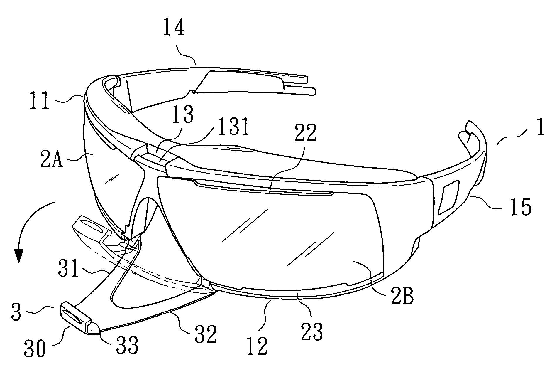
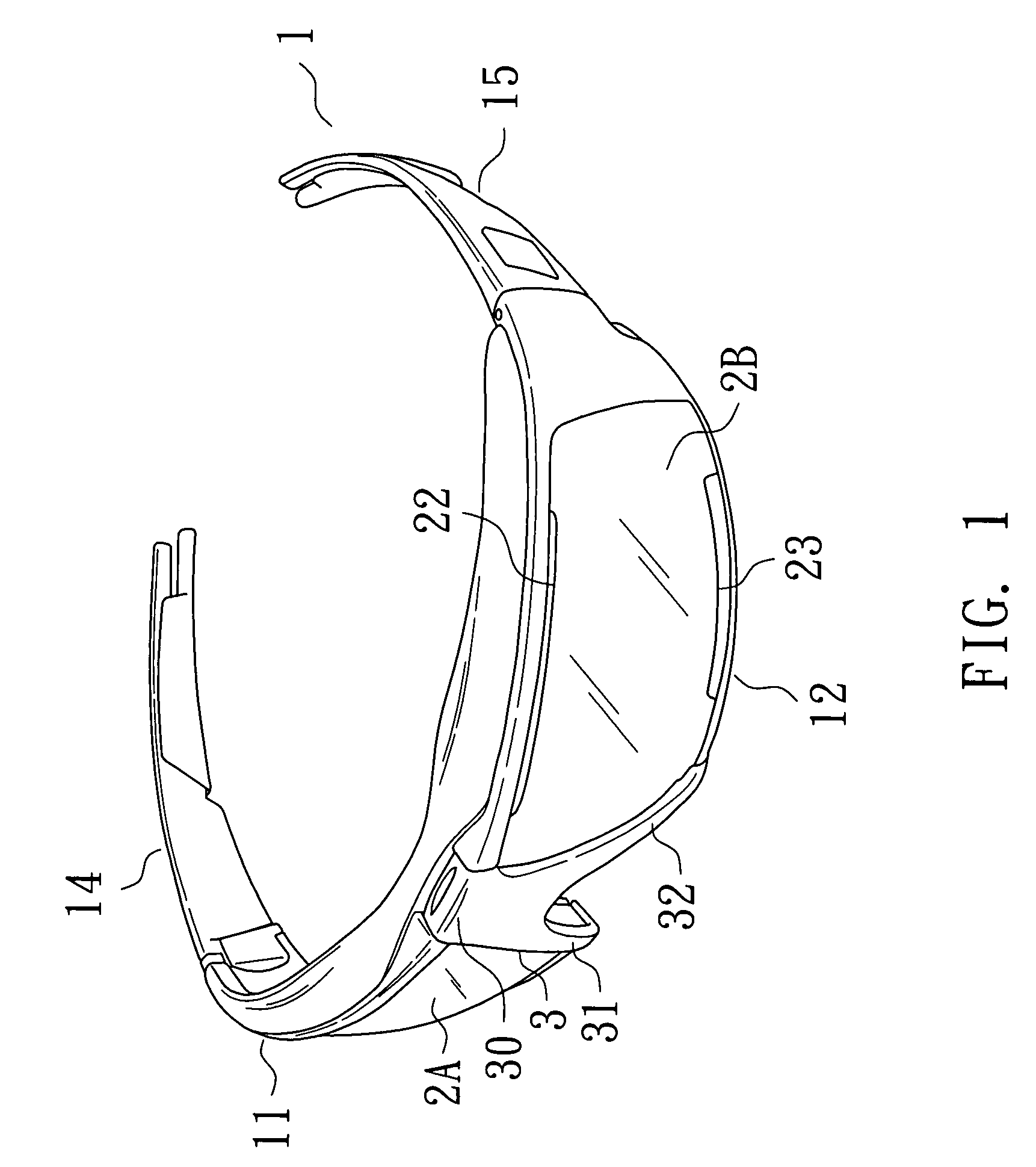
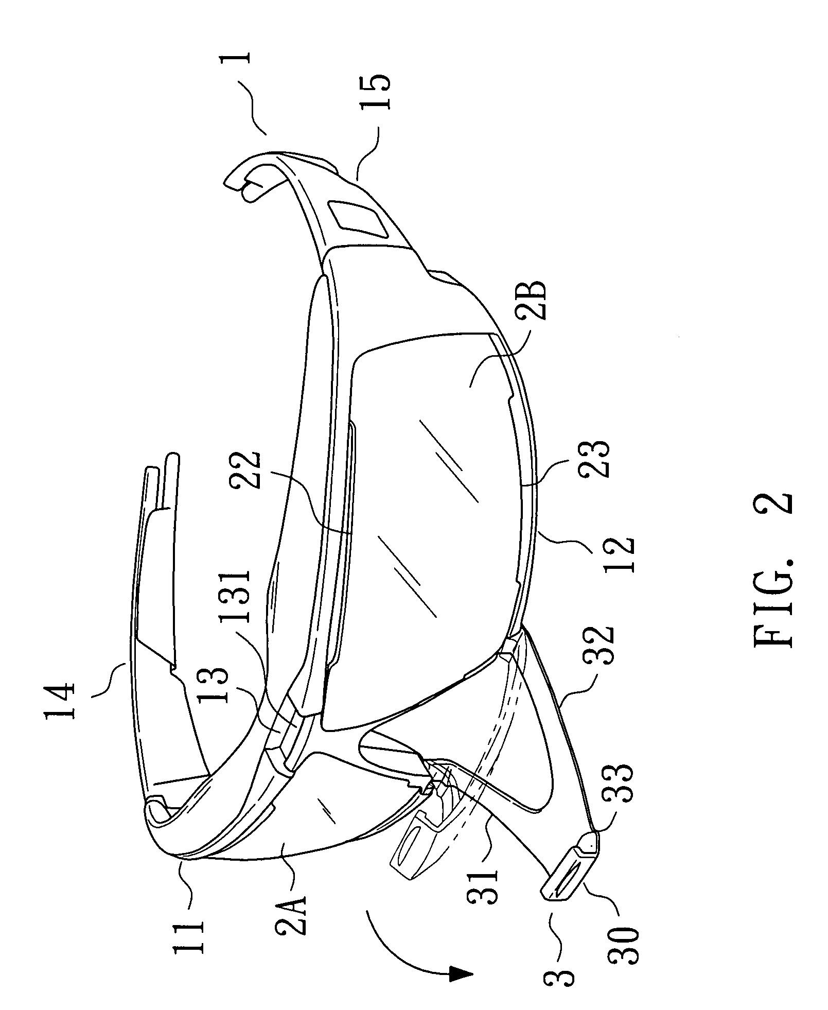
[0019]A pair of glasses according to the preferred teachings of the present invention is shown in the drawings. According to the preferred form shown, the pair of glasses includes a frame 1 having two sides. A temple 14, 15 extends rearward from each side of the frame 1. The temples 14 and 15 can be replaced by other wearing elements such as a head strap. The frame 1 includes two lens receiving portions 11 and 12 each defining a compartment for receiving a lens 2A, 2B. Each lens receiving portion 11, 12 includes an outer stop 122 formed on an outer section of an inner periphery defining the compartment. With reference to FIG. 3B, the outer stop 122 includes a lateral edge 122A in contact with an outer lateral edge 26 of one of the lenses 2A and 2B and a front edge 122B in contact with an outer end 28 of a front face of one of the lenses 2A and 2B. Disengagement of the lens 2A, 2B from the outer section of the inner periphery of the lens receiving portion 11, 12 is avoided (see FIG. ...


PUM


Abstract

A pair of glasses includes two lenses received in two lens receiving portions of a frame. A groove is defined in the frame and between tops of the lens receiving portions. Each lens receiving portion includes outer and rear stops for retaining the lenses. A movable stop includes two legs movably coupled with lower ends of inner sides of the lens receiving portions. The movable stop is movable between an engaged position in which a top portion of the movable stop is engaged with the groove and in which forward inclination of the lenses are stopped by the legs and a disengaged position in which the top portion of the movable stop is disengaged from the groove of the frame and in which insertion or removal of the lenses into or from the lens receiving portions is allowed.

Description

BACKGROUND OF THE INVENTION[0001]The present invention relates to an assembling structure for a pair of glasses and, more particularly, to an assembling structure between two lenses and a frame of a pair of glasses.[0002]A typical pair of glasses includes a frame having two lens receiving portions and two lenses embedded in or forcibly inserted into the lens receiving portions. Another typical pair of glasses includes a single lens embedded in a frame having a single lens receiving portion. In either case, the lens has a size slightly larger than that of the lens receiving portion, and the lens receiving portion is made of resilient material to allow forcible insertion of the lens. However, breakage of the lens and / or the lens receiving portion occurs easily due to improper application of force.[0003]In a variation, a perimeter of the lens receiving portion has a movable portion that can be moved to an open position to allow easy insertion of the lens, and screws are utilized to fix...

Claims


Application Information

Patent Timeline
Patent Type & Authority Patents(United States)
IPC IPC(8): G02C1/00
CPCG02C1/06G02C11/08G02C5/02G02C2200/08
Inventor CHEN, CHIH-MING
Owner CHEN CHIH MING
Why Eureka
Try Eureka