Methods of drilling wellbores using variable density fluids comprising coated elastic particles

a technology of elastic particles and fluids, applied in the field of variable density subterranean treatment fluid compositions, can solve the problems of uncontrolled blowout, uncontrolled flow of drilling fluids, and high drilling cos

Inactive Publication Date: 2009-01-27
HALLIBURTON ENERGY SERVICES INC
View PDF97 Cites 79 Cited by
  • Summary
  • Abstract
  • Description
  • Claims
  • Application Information

AI Technical Summary

Benefits of technology

[0010]Another example of a method of the present invention is a method of avoiding the loss of circulation of a well fluid in a subterranean formation, comprising the step of adding to the well fluid a portion of elastic particles, the elastic particles being capable of varying in volume with pressure.

Problems solved by technology

Kicks may be both dangerous and very costly to drillers.
Such fracturing of the formation could result in flow of drilling fluids out of the borehole into the formation (commonly referred to as “lost circulation”), or possibly an uncontrolled blowout of the formation fluids, and in some cases, fluids and particulates.
The formulation of a drilling fluid satisfying these limitations is often complicated because the riser connecting the borehole to the drilling rig must often be quite long, particularly when drilling in deep water applications.
Further complicating the formulation of the drilling fluid, at subsequent depths the hydrostatic and friction forces may be insufficient to prevent fluid influx from the formation.
Efforts to overcome this difficulty in drilling deep water wells have met with limited success.
This strategy is problematic because the installation of additional casing usually correspondingly reduces the usable diameter of the borehole.
Furthermore, the installation of additional strings of casing may add greatly to the expense and complication of completing the well.
However, this method may not achieve desirable results because of the great expense involved in procuring and installing the system of risers and pumps.
However, this method is problematic, inter alia, because of the cost and mechanical difficulty of injecting these spheres at the sea floor, and then separating them from the drilling fluid at the surface.
Furthermore, the incompressible nature of these rigid spheres tends to cause them to crush at the pressures typically encountered in deepwater drilling; accordingly, such rigid spheres are typically unable to reduce the density of the drilling fluid while it travels upward toward the surface.
Analogous problems exist in other subterranean operations.
For example, a fracturing or acidizing operation may involve additional expense in removing the spent fracturing or acidizing fluid from the well bore after the operation is conducted, due in part to the fixed-density nature of such fluids, which may necessitate additional manpower or pumping equipment to remove such fluid in a timely fashion.

Method used


Image

  • Methods of drilling wellbores using variable density fluids comprising coated elastic particles

Examples


example 1

[0036]The effect of the elastic particles on the variable density fluids of the present invention may be illustrated by considering a hypothetical drilling fluid of the present invention comprising 20% elastic particles by volume, the elastic particles having a specific gravity of about 0.41 and an isothermal compressibility factor of about 1.5×10⁻⁴ (1 / psi), and further comprising 80% base fluid by volume, the base fluid having a density of about 10 lb / gallon. The following equations may be used to calculate the density of the variable density fluid at different depths.

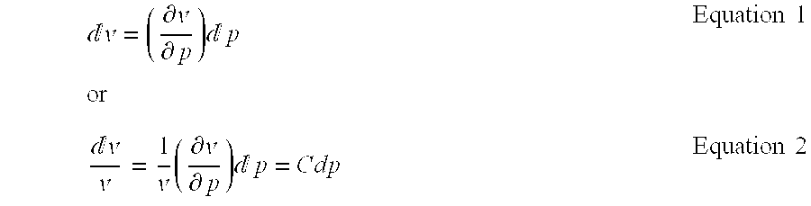
[0037]The change in volume of the elastic particle as the external pressure changes may be determined from the relationship:

[0038]ⅆ𝓋=(∂𝓋∂p)⁢ⅆp⁢⁢orEquation⁢⁢1ⅆ𝓋𝓋=1𝓋⁢(∂𝓋∂p)⁢ⅆp=CdpEquation⁢⁢2

In Equation 2, the value “C” is the compressibility of the elastic particle. If the elastic particle is subjected to a change in pressure of dp, then the new volume of the elastic particle is given by:

Vnew=Vold+dv  Equation 3

an...


PUM

PropertyMeasurementUnit
pressuresaaaaaaaaaa
temperaturesaaaaaaaaaa
specific gravityaaaaaaaaaa

Abstract

The present invention provides variable density fluid compositions and methods for using such compositions in a subterranean formation. One exemplary embodiment of the variable density fluid compositions of the present invention comprises a variable density fluid comprising: a base fluid; and a portion of elastic particles, the elastic particles having an isothermal compressibility factor in the range of from about 1.5×10⁻³ (1 / psi) to about 1.5×10⁻⁹ (1 / psi).

Description

BACKGROUND OF THE INVENTION[0001]The present invention relates to subterranean treatment fluids. In particular, the present invention relates to variable density subterranean treatment fluid compositions and methods for using such compositions.[0002]A treatment fluid may be used in a subterranean formation in a variety of ways. For example, a fluid may be used to drill a borehole in a subterranean formation, to stimulate a well bore in a subterranean formation, and to clean up a well bore in a subterranean formation, as well as for numerous other purposes. The process of drilling a well typically requires the use of a treatment fluid referred to as a “drilling fluid.” During the drilling process, the drilling fluid passes down through the inside of the drill string, exits through the drill bit, and returns to the drill rig through the annulus between the drill string and well bore. The circulating drilling fluid, inter alia, lubricates the drill bit, carries drill cuttings to the su...

Claims


Application Information

Patent Timeline
Patent Type & Authority Patents(United States)
IPC IPC(8): E21B21/00B01F3/12C09K8/24
CPCC09K8/03C09K8/536C09K8/70C09K8/92
Inventor RAVI, KRISHNA M.WHITFILL, DONALD L.REDDY, B. RAGHAVA
Owner HALLIBURTON ENERGY SERVICES INC
Why Eureka
Try Eureka