
Method for grouping transmission antennas in mobile communication system including multiple transmission/reception antennas

a mobile communication system and antenna technology, applied in electromagnetic wave modulation, wireless commuication services, instruments, etc., can solve the problems of pushed to operational limits, current channel coding schemes, and inability to transmit multimedia high quality in addition to voice, so as to increase communication capacity

Active Publication Date: 2009-01-27
SAMSUNG ELECTRONICS CO LTD +1
View PDF26 Cites 98 Cited by
  • Summary
  • Abstract
  • Description
  • Claims
  • Application Information

AI Technical Summary

Benefits of technology

[0015]Accordingly, the present invention has been made to solve the above-mentioned problems occurring in the prior art. It is therefore an object of the present invention to provide a method for grouping multiple transmission antennas to increase communication capacity in a mobile communication system which includes the multiple transmission antennas and multiple reception antennas.

Problems solved by technology

However, current mobile communication systems do not have the capacity to transmit high quality multimedia in addition to voice.
As a result, current channel coding schemes that need to transmit more and more data in the same amount of data are pushed to operational limits and cannot satisfy the need for greater data transmission at a lower error rate.
However, in general, the spatial multiplexing scheme is limited because the number of antennas for a transmitter must be smaller than the number of antennas for a receiver.
Therefore, when a base station using the spatial multiplexing scheme transmits data via a forward link, there is a limitation in the whole communication capacity of the mobile communication system due to the limited number of reception antennas of the mobile terminal, so that it is difficult to realize a transmitter according to the spatial multiplexing scheme.
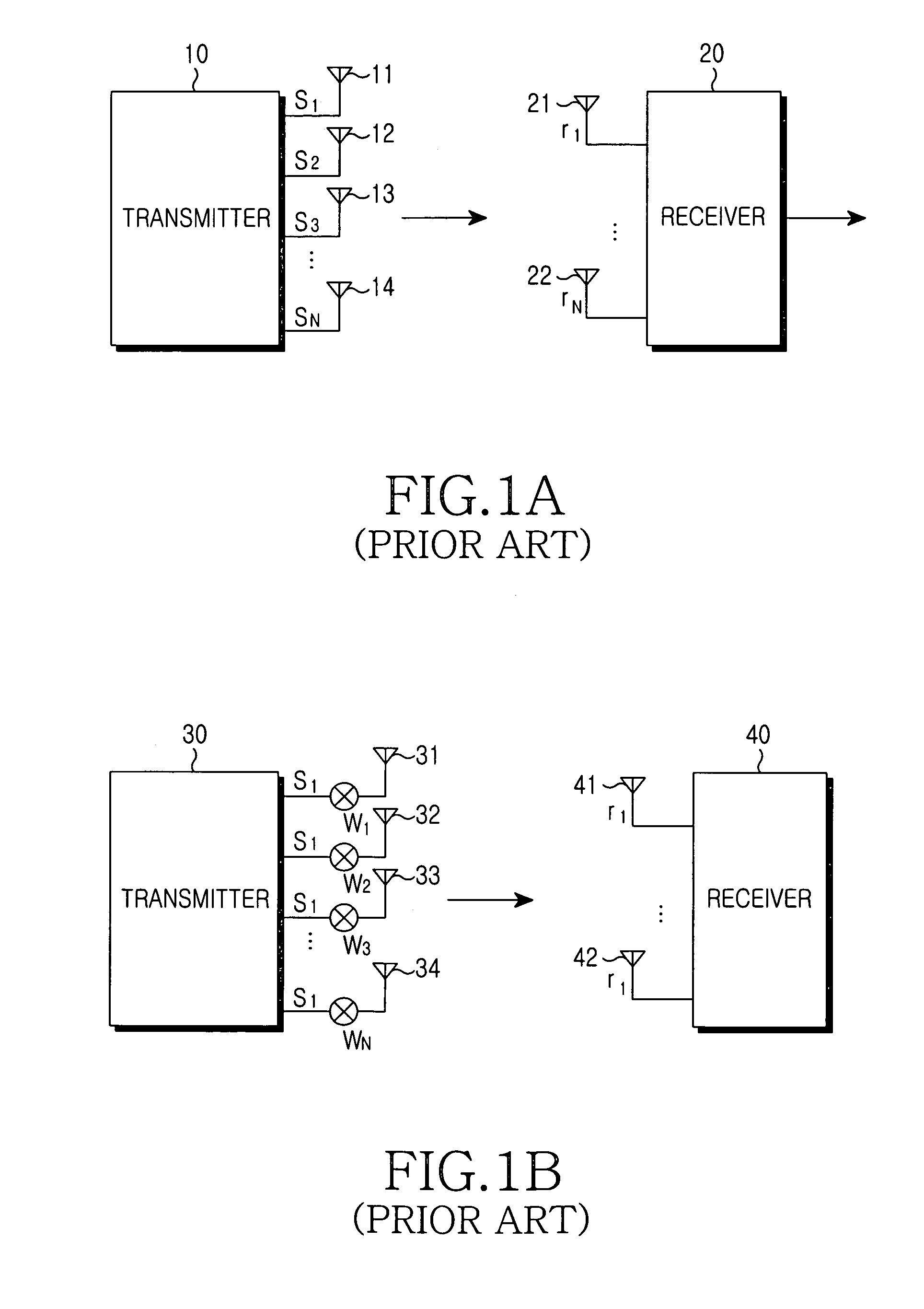
But there is a disadvantage in that frequency efficiency is deteriorated because the same symbols (S1) are simultaneously transmitted through a plurality of antennas.
That is, the beamforming scheme has reduced communication capacity.
Therefore, a transmission construction according to the above-mentioned beamforming scheme may deteriorate communication capacity of the next-generation mobile communication system, which will actually require faster data transmission rates.

Method used


Image

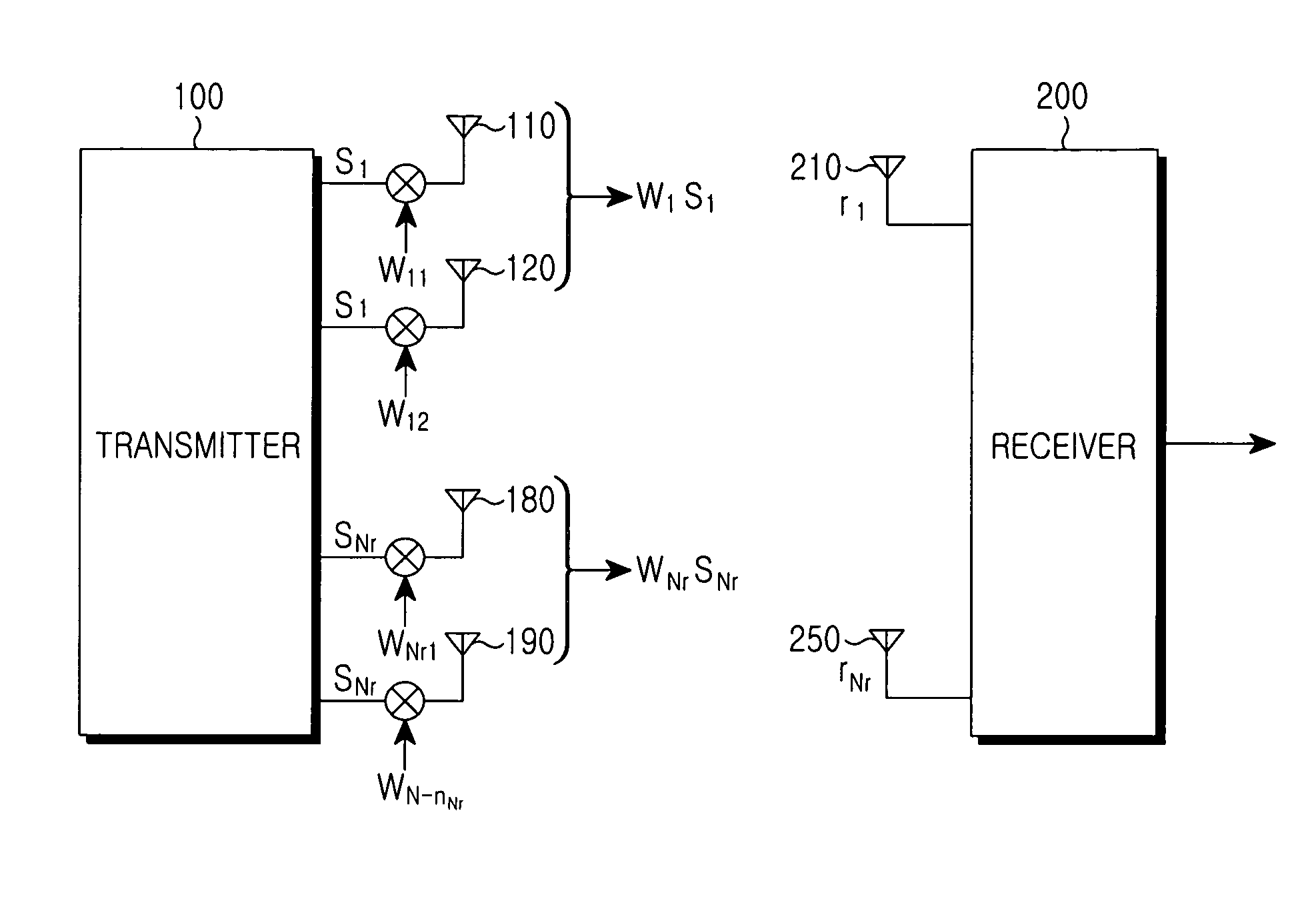
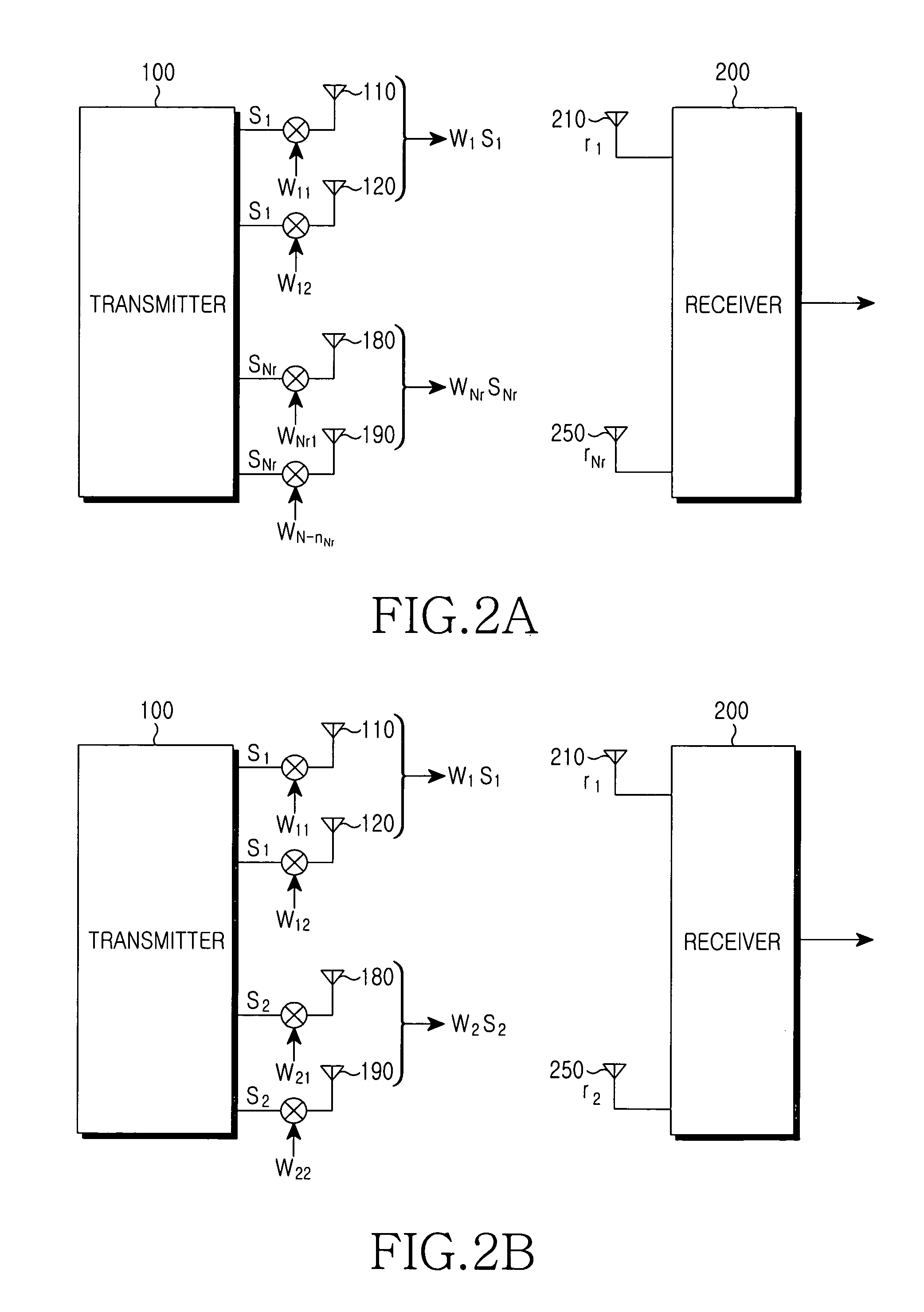
  • Method for grouping transmission antennas in mobile communication system including multiple transmission/reception antennas
  • Method for grouping transmission antennas in mobile communication system including multiple transmission/reception antennas
  • Method for grouping transmission antennas in mobile communication system including multiple transmission/reception antennas

Examples


Embodiment Construction

[0027]Hereinafter, a preferred embodiment according to the present invention will be described with reference to the accompanying drawings. In the following description of the present invention, a detailed description of known functions and configurations incorporated herein will be omitted when it may obscure the subject matter of the present invention.

[0028]The present invention is proposed to provide a method grouping multiple transmission antennas by a base station in a mobile communication system which includes the multiple transmission antennas and multiple reception antennas.

[0029]The base station groups the multiple transmission antennas by a channel covariance matrix, transmits different symbols through different groups of transmission antennas, and transmits the same symbol through the same group of transmission antennas. That is, the base station transmits different symbols according to the groups, thereby increasing the communication capacity of the mobile communication ...


PUM


Abstract

Disclosed is a method for configuring transmission antenna groups in a mobile communication system with multiple transmission antennas and multiple reception antennas. The method includes the steps of: receiving a first matrix having a size of ‘Nt×Nt’, which corresponds to Nt number of transmission antennas, fedback from the mobile terminal, generating combinations of sub-matrixes of the first matrix corresponding to Nr number of reception antennas, and calculating sums of maximum eigenvalues; determining combinations of the sub-matrixes having a maximum value from among the calculated sums of eigenvalues to be transmission antenna groups for the Nt number of transmission antennas; and transmitting different relevant symbols from each other through the transmission antenna groups.

Description

PRIORITY[0001]This application claims priority to an application entitled “Method for Grouping Transmission Antennas in Mobile Communication System Including Multiple Transmission / Reception Antennas” filed in the Korean Intellectual Property Office on Nov. 13, 2003 and assigned Serial No. 2003-80354, the contents of which are incorporated herein by reference.BACKGROUND OF THE INVENTION[0002]1. Field of the Invention[0003]The present invention relates to a method for grouping multiple transmission antennas to increase communication capacity in a mobile communication system which includes multiple transmission antennas and multiple reception antennas.[0004]2. Description of the Related Art[0005]Conventional mobile communication systems have been developed mainly for voice transmission with a channel coding technique used to overcome the deterioration of channels in a radio environment. However, current mobile communication systems do not have the capacity to transmit high quality mult...

Claims


Application Information

Patent Timeline
Patent Type & Authority Patents(United States)
IPC IPC(8): H04M1/00H04B7/02H04B7/06H04B7/08H04Q7/00
CPCH04B7/0691H04B7/0874H04B7/02
Inventor KIM, EUNG-SUNLEE, JONG-HYEUKCHUNG, JAE-HAKKIM, HO-JINCHUN, JOO-HWANLEE, KYUNG-CHUNKIM, IL-HAN
Owner SAMSUNG ELECTRONICS CO LTD
Learn More