
Method of determining ink ejection method, printing apparatus, and method of manufacturing printing apparatus

a printing apparatus and ink ejection technology, applied in printing, digital output to print units, inking apparatus, etc., can solve problems such as difficulty in integral form, inability to print images, and high cost of ink ejection heads, and achieve the effect of suppressing density unevenness

Active Publication Date: 2009-02-03
SEIKO EPSON CORP
View PDF8 Cites 7 Cited by
  • Summary
  • Abstract
  • Description
  • Claims
  • Application Information

AI Technical Summary

Benefits of technology

The invention is about a printing apparatus, system, and method that can reduce unevenness in image density caused by overlapping nozzles. The method involves determining an ink ejection method based on the density of the image formed by the nozzles in the overlap area. This allows for more precise and accurate ink ejection, resulting in better quality images. The printing apparatus and system include a nozzle unit with multiple rows of nozzles arranged parallel to each other, and the nozzles in one row are overlapped with those in another row to form an overlap area. The ink ejection method is determined based on the density of the image formed by the nozzles in this overlap area. This technology can improve the performance and reliability of printing apparatuses and systems.

Problems solved by technology

However, it is difficult to integrally form, at high precision, an ink ejection head having nozzles at the entire area of the width (210 mm) in the width direction of A4 size paper, for example.
Furthermore, even if produced, such an ink ejection head is very expensive.
Thus, even when an image with uniform density is to be printed, density unevenness may be caused in a printed image.

Method used


Image

  • Method of determining ink ejection method, printing apparatus, and method of manufacturing printing apparatus
  • Method of determining ink ejection method, printing apparatus, and method of manufacturing printing apparatus
  • Method of determining ink ejection method, printing apparatus, and method of manufacturing printing apparatus

Examples


Embodiment Construction

[0049]At least the following matters will be made clear by the explanation in the present specification and the description of the accompanying drawings.

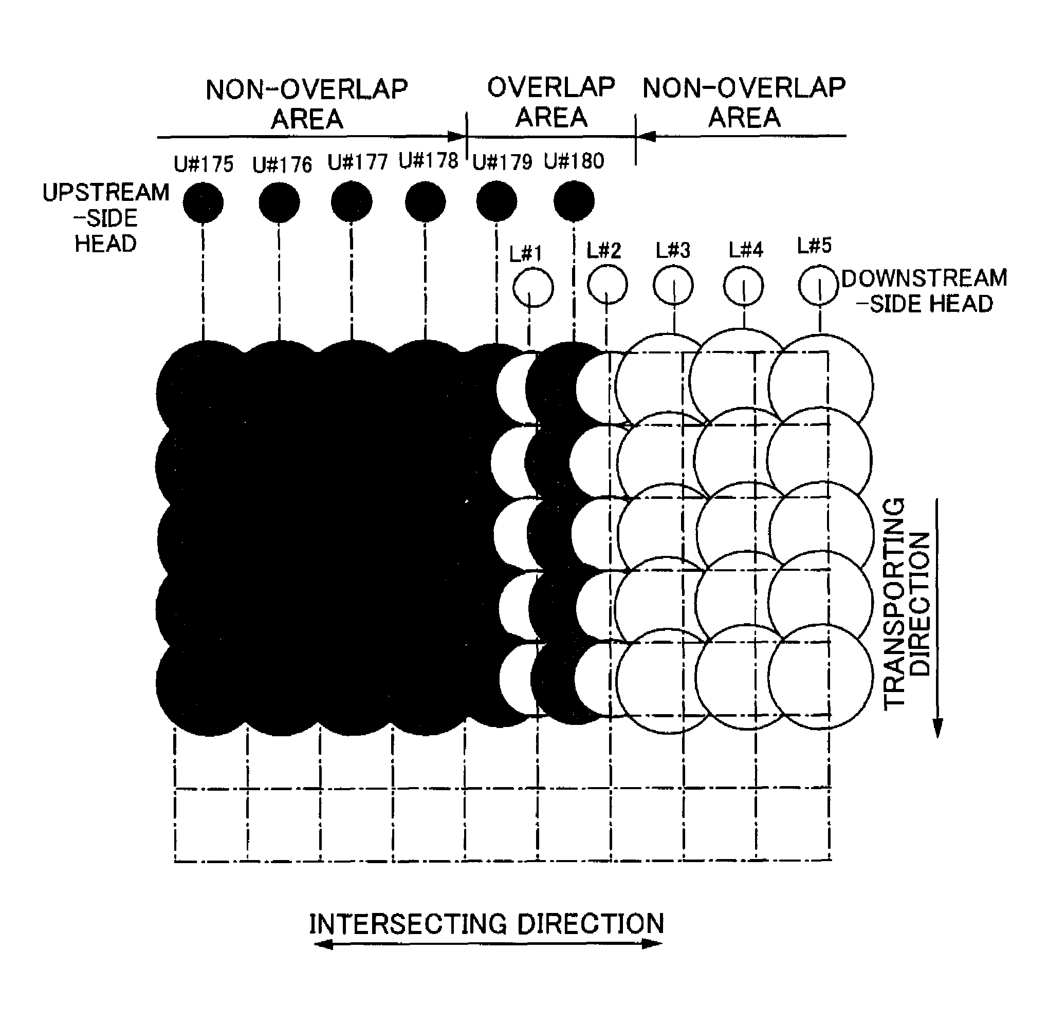
[0050]A method for determining an ink ejection method comprises:[0051]transporting a medium in a transporting direction;[0052]forming an image with a nozzle unit having a plurality of nozzle rows in which a plurality of nozzles for ejecting ink are arranged at a predetermined interval in an intersecting direction intersecting the transporting direction,[0053]wherein the plurality of nozzle rows are arranged parallel to each other,[0054]one end side in the intersecting direction in a particular nozzle row and the other end side in the intersecting direction in another nozzle row are overlapped with each other in the transporting direction so as to form an overlap area, and[0055]in the overlap area, the nozzle in the particular nozzle row and the nozzle in the other nozzle row are at different positions in the intersecting direction; ...


PUM


Abstract

Density unevenness caused in an image formed with an overlap portion of nozzles is suppressed. For this purpose, a method of determining an ink ejection method includes: transporting a medium in a transporting direction; forming an image with a nozzle unit having a plurality of nozzle rows in which a plurality of nozzles for ejecting ink are arranged at a predetermined interval in an intersecting direction intersecting the transporting direction, wherein the plurality of nozzle rows are arranged parallel to each other, one end side in the intersecting direction in a particular nozzle row and the other end side in the intersecting direction in another nozzle row are overlapped with each other in the transporting direction so as to form an overlap area, and in the overlap area, the nozzle in the particular nozzle row and the nozzle in the other nozzle row are at different positions in the intersecting direction; and determining an ink ejection method from the nozzles in the overlap area, based on a density of the image.

Description

CROSS-REFERENCE TO RELATED APPLICATIONS[0001]The present application claims priority upon Japanese Patent Application No. 2006-110901 filed on Apr. 13, 2006, which is herein incorporated by reference.TECHNICAL FIELD[0002]The present invention relates to a method of determining an ink ejection method, a printing apparatus for forming an image by ejecting ink onto a medium, and a method of manufacturing a printing apparatus.RELATED ART[0003]Inkjet printers are known as one type of printing apparatus for forming an image by ejecting ink onto a medium. Among such inkjet printers, there is a printer having an ink ejection head in which nozzles are provided at the entire area in a width direction intersecting a transporting direction of a medium on which an image is to be formed. In a printer provided with nozzles at the entire area in the width direction of a medium, the interval between the nozzles often corresponds to the resolution of an image, and thus the positional precision of the...

Claims


Application Information

Patent Timeline
Patent Type & Authority Patents(United States)
IPC IPC(8): B41J29/38
CPCB41J2/155B41J2/2132B41J2202/20B41J2/07B41J29/38G06F3/12
Inventor SUDO, NAOKINUNOKAWA, HIROKAZU
Owner SEIKO EPSON CORP
Learn More