
Keyboard apparatus

a keyboard and key technology, applied in the field of keyboard apparatus, can solve the problems of limited upward pivoting movement of each key structure, and achieve the effect of good key touch feeling

Active Publication Date: 2009-02-03
YAMAHA CORP
View PDF17 Cites 31 Cited by
  • Summary
  • Abstract
  • Description
  • Claims
  • Application Information

AI Technical Summary

Benefits of technology

The present invention provides an improved keyboard apparatus that can provide a good key touch feeling and allow for the installation of a wiring cable without interfering with the hammer structures. The keyboard apparatus includes a plurality of keys, a key frame, and a circuit board with switches corresponding to the keys. A hammer structure is pivotally provided on the key frame and in interlocked relation to depression operation of a corresponding key. An upper stopper is provided on the key frame and defines an upper end limit of pivoting movement of the hammer structures. The wiring cable connected to the circuit board is installed in a way that it runs below the key support section of the key frame, passes through an opening portion, and extends upwardly beyond the upper stopper so that it is led out to a region behind the key frame. This arrangement avoids interference between the cable and the hammer structures. The keyboard apparatus also includes an upwardly-opening wall section that holds the wiring cable and prevents interference with surrounding components. The invention allows for a cost-effective and simplified construction for supporting the keys.

Problems solved by technology

Besides, upward pivoting movement of each of the key structures is limited by the upper stopper.

Method used


Image

  • Keyboard apparatus
  • Keyboard apparatus
  • Keyboard apparatus

Examples


Embodiment Construction

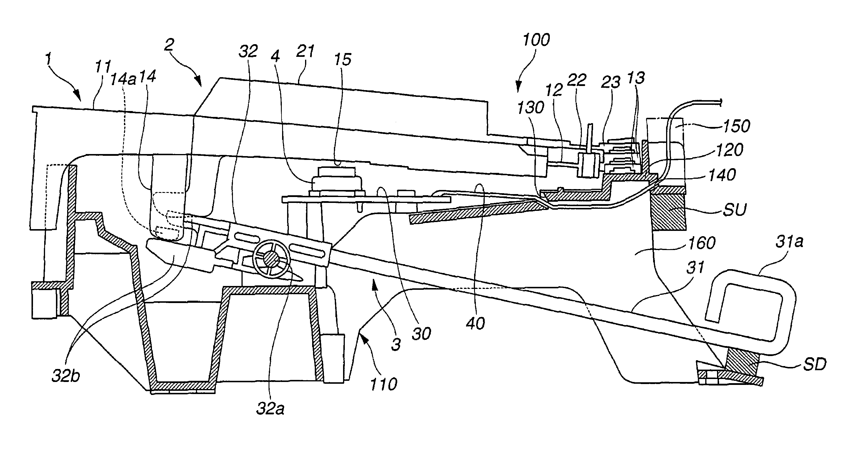
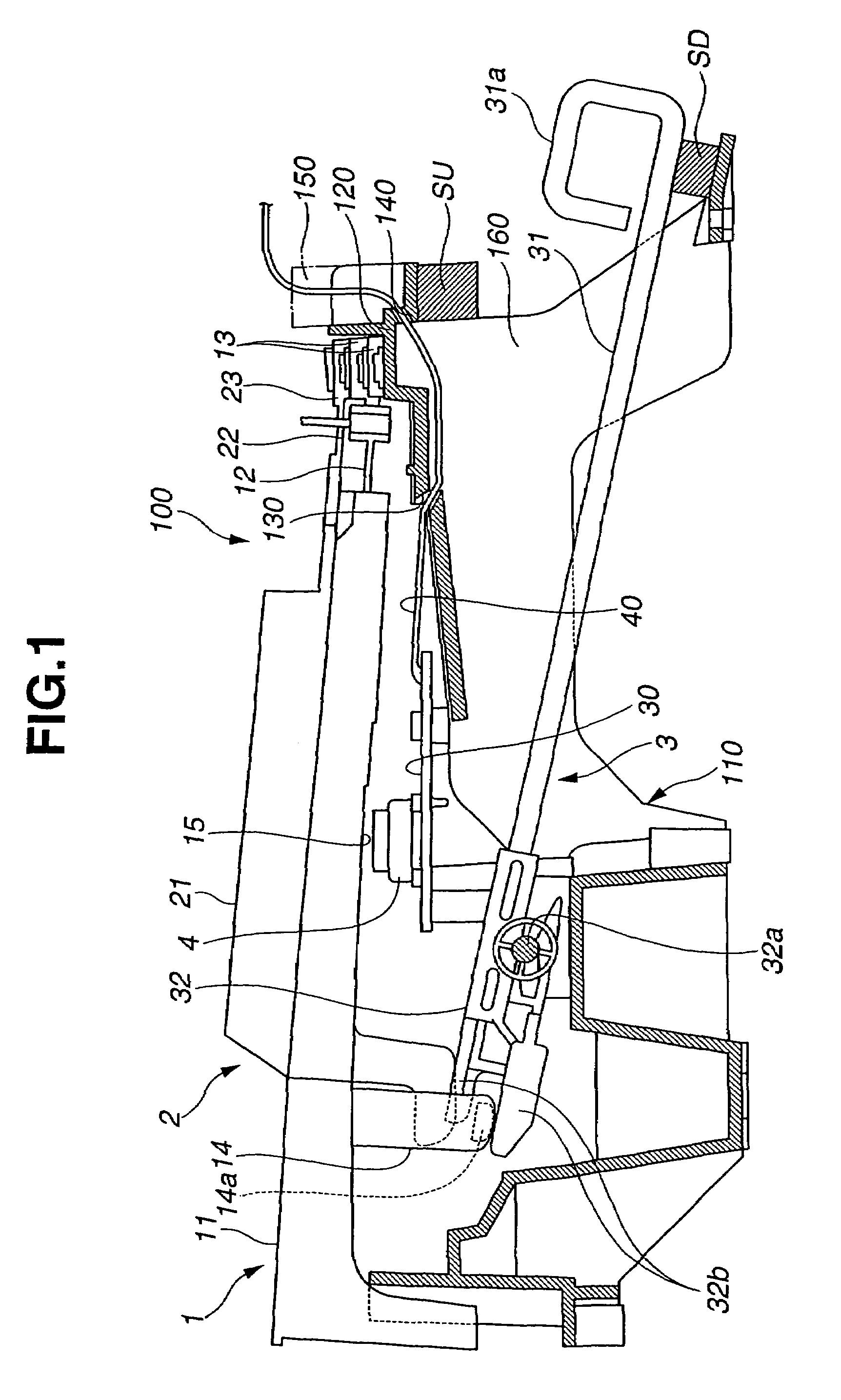
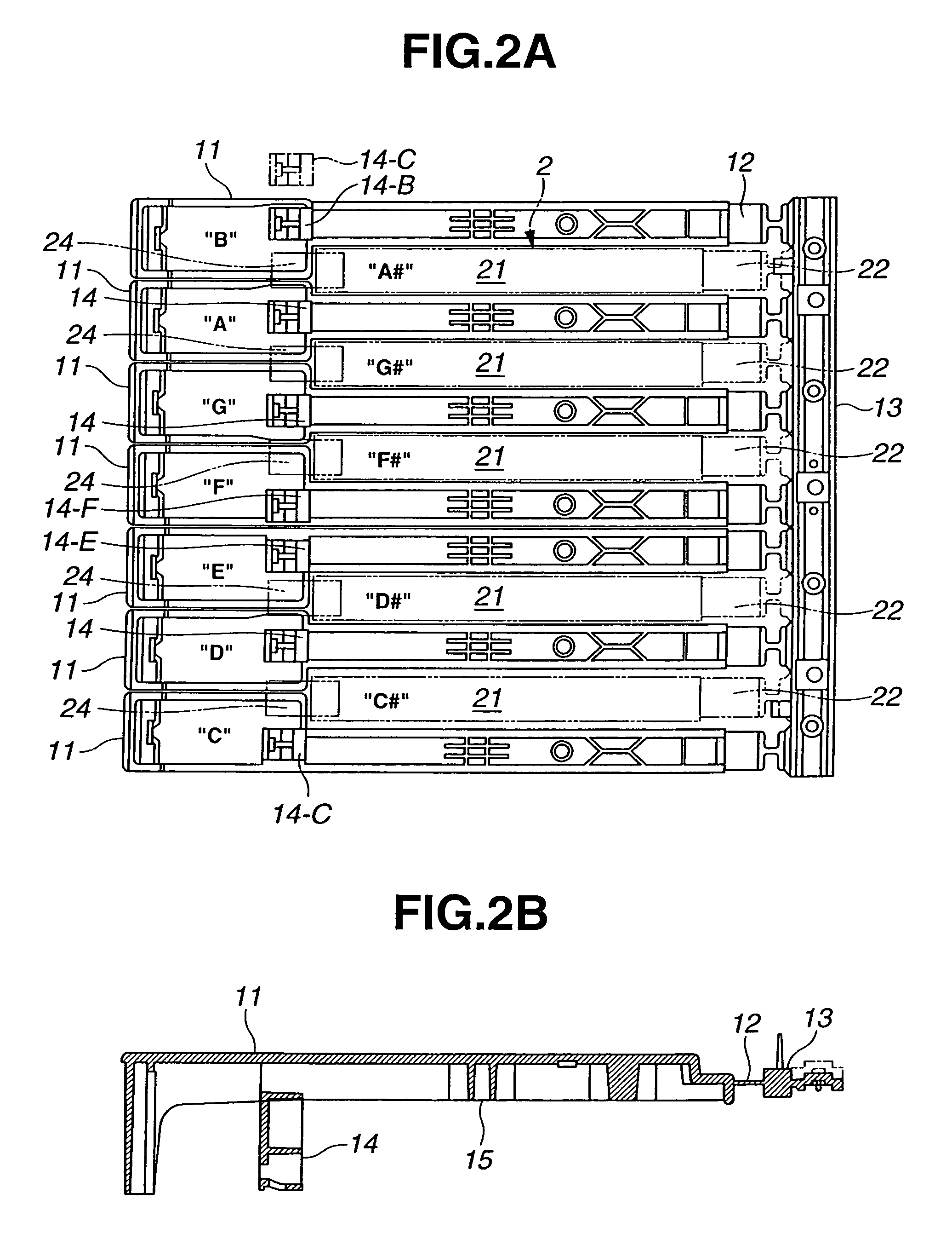
[0018]FIG. 1 is a sectional side view showing essential parts of a keyboard apparatus in accordance with an embodiment of the present invention, FIGS. 2A and 2B are a plan view and sectional side view, respectively, of a white key unit in the keyboard apparatus, FIGS. 3A and 3B are exploded plan views of the white key unit, and FIG. 4 is a sectional side view of an electronic musical instrument employing the keyboard apparatus of the present invention. Note that a left side in each of FIGS. 1-5 is a side closer to a human player of the keyboard and a direction perpendicular to the sheet of each of FIGS. 1 to 4 is a direction in which keys of the keyboard apparatus are arranged (i.e., key-arranged direction). In the following description, a side of the electronic musical instrument and keyboard apparatus closer to the human player playing the keyboard will be referred to as “front”, while the opposite side from the human player will be referred to as “rear”. Further, in the following...


PUM


Abstract

Key frame has a key support section that pivotably supports thereon a plurality of keys. Hammer structures are pivotably provided in corresponding relation to and below the keys, each of which pivots in interlocked relation to depression operation of a corresponding one of the keys. On a rear portion of the key frame, there is provided an upper stopper that is elongated and extends in a direction where the keys are arranged. The upper stopper defines an upper end limit of pivoting movement of each of the hammer structures. Opening portion is formed between the key support section and the upper stopper. Wiring cable connected to a circuit board, having switches corresponding to the keys, is run below the key support section, then passed through the opening portion and thence drawn upwardly beyond the upper stopper so that it is led out to a region above the upper stopper.

Description

BACKGROUND OF THE INVENTION[0001]The present invention relates to keyboard apparatus equipped with hammer structures pivotably provided beneath individual keys.[0002]Examples of keyboard apparatus of the type equipped with hammer structures pivotably provided beneath individual keys are disclosed in Japanese Patent Application Laid-open Publication Nos. H9-198037 (hereinafter referred to as “patent literature 1”) and 2003-42206 (hereinafter referred to as “patent literature 2”). In the keyboard apparatus disclosed in patent literature 1 identified above, each of white and black keys is pivotably supported at its rear end portion by a frame and normally biased by a leaf spring. Further, a pivot lever, including a lever base and weight, is provided as a hammer structure beneath each of the keys, and the pivot lever is driven by a driving section provided on the key. The key is returned to its original position by the resilient force of the leaf spring as depression of the key is relea...

Claims


Application Information

Patent Timeline
Patent Type & Authority Patents(United States)
IPC IPC(8): G10H1/00
CPCG10C3/12
Inventor NISHIDA, KENICHI
Owner YAMAHA CORP
Learn More