Eureka AIR delivers breakthrough ideas for toughest innovation challenges, trusted by R&D personnel around the world.

Method and apparatus for estimating an in-focus position

a technology of in-focus position and apparatus, which is applied in the field of method of estimating in-focus position of targets, can solve the problems of reducing the productivity of apparatuses, requiring rapid changes in focus that require many points to be measured, so as to improve the quality of image information for focus levels

Active Publication Date: 2009-02-03
FFEI LTD
View PDF11 Cites 32 Cited by
  • Summary
  • Abstract
  • Description
  • Claims
  • Application Information

AI Technical Summary

Benefits of technology

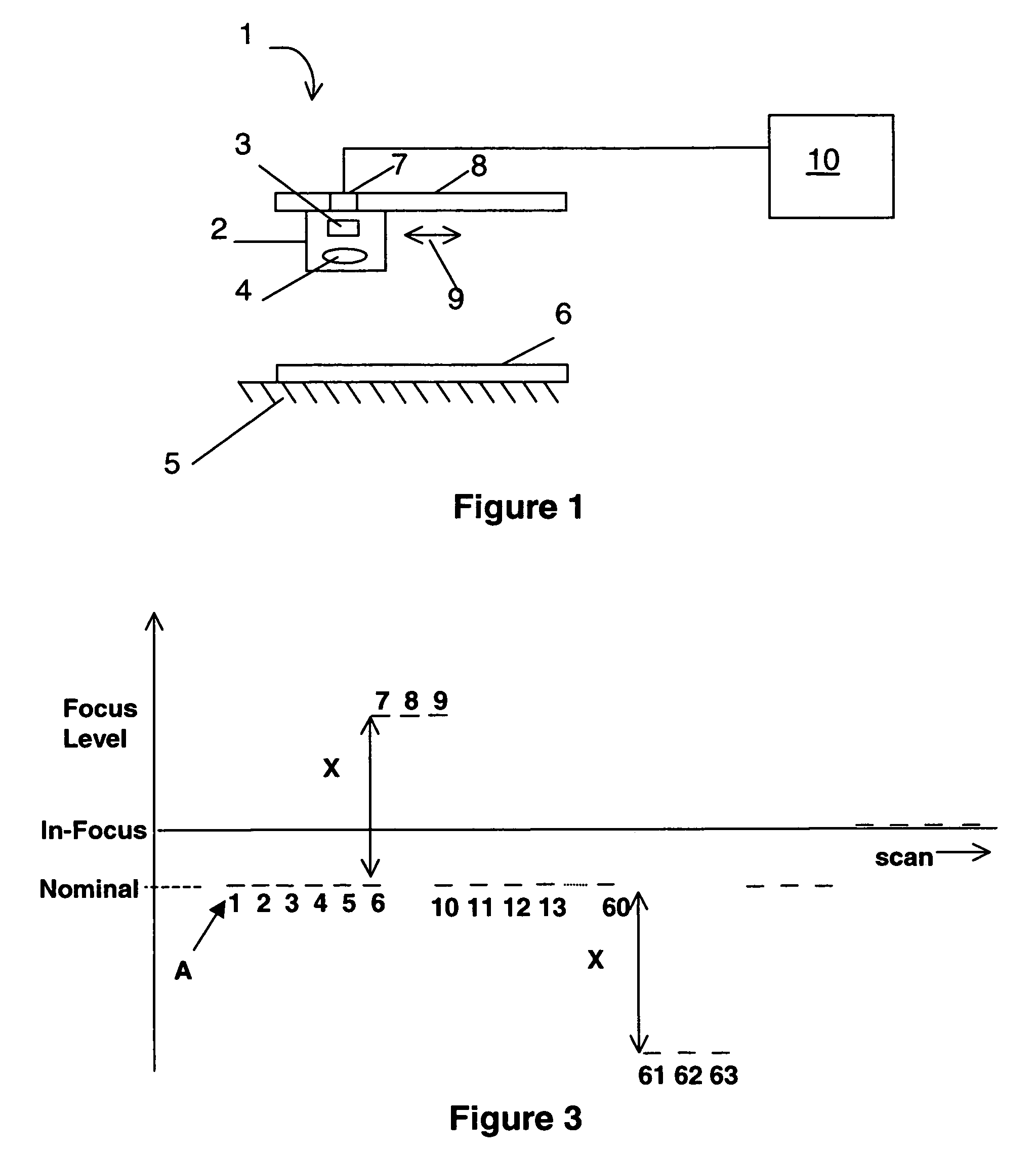
[0009]We have realised that the in-focus position can actually be estimated during the performance of a scan itself. By sacrificing some of the nominally in-focus image information it is possible to estimate the in-focus position by obtaining image information at one or more further focus levels which are dissimilar to the nominal focus level. The information obtained at the further focus level and the nominal focus level can then be used to determine the in-focus position. This is advantageous in that the in-focus position can be estimated at a number of different points during the scan itself. Furthermore there is no need for pre-scanning or any mapping to be performed and therefore the focussing can be performed on-the-fly. Provided sufficiently small amounts of image information are obtained whilst at the further focus level(s), the overall quality of the image information obtained can be maintained by modifying the further focus level image information in accordance with surrounding image information obtained at the nominal focus level.
[0010]Preferably two or more further focus levels are used, and these are preferably positioned straddling the nominal focus level. Therefore when two further levels are provided, one is provided on each “side” of the nominal focus level. This is not essential and indeed the separation in focus between the further and nominal levels may be different for each further level. Image scanning is normally performed using a detector array from which scan lines of image information are obtained so as to build up the resultant image. Since focussing is normally a mechanical procedure (at least for the focussing of light), the focus levels are preferably separated from each other by a number of scan lines. This allows time for the apparatus to be adjusted between the various focus levels. The further focus levels may therefore be mutually separated by about 50 scan lines.
[0015]It is preferable for the nominal focus level to be as close to the in-focus position as possible. Prior to performing the scan, a starting focus position may be evaluated so as to approximately or accurately determine the in-focus position for the target and the nominal focus level may be set accordingly to correspond to this.
[0016]As mentioned earlier, when the image information is obtained at the further focus level(s), the quality of the image information for the focus levels may be improved by modifying said image information by interpolation using adjacent image information obtained at the nominal focus level. In the case where scan lines are used, the interpolation may be performed by using weighted contributions of a number of the nearby scan lines from the adjacent nominal focus level image information.

Problems solved by technology

The drawback of this process is that rapid changes in focus require many points to be measured before scanning.
This is of course time-consuming and can lower the productivity of the apparatus significantly.

Method used


Image

  • Method and apparatus for estimating an in-focus position
  • Method and apparatus for estimating an in-focus position
  • Method and apparatus for estimating an in-focus position

Examples


Embodiment Construction

[0032]An example image scanning apparatus is shown generally at 1 in FIG. 1. This comprises a scan head 2 comprising a photo-detector array 3 and an adjustable focus system 4. A platen 5 is provided upon which is positioned a target to be scanned 6. A drive mechanism 7 attaches the scan head to a track 8 such that the scan head can be moved with respect to the target 6 as indicated by the arrows 9. The image scanning apparatus is controlled using a controller 10 which may comprise programmable logic, a dedicated processor or a computer system.

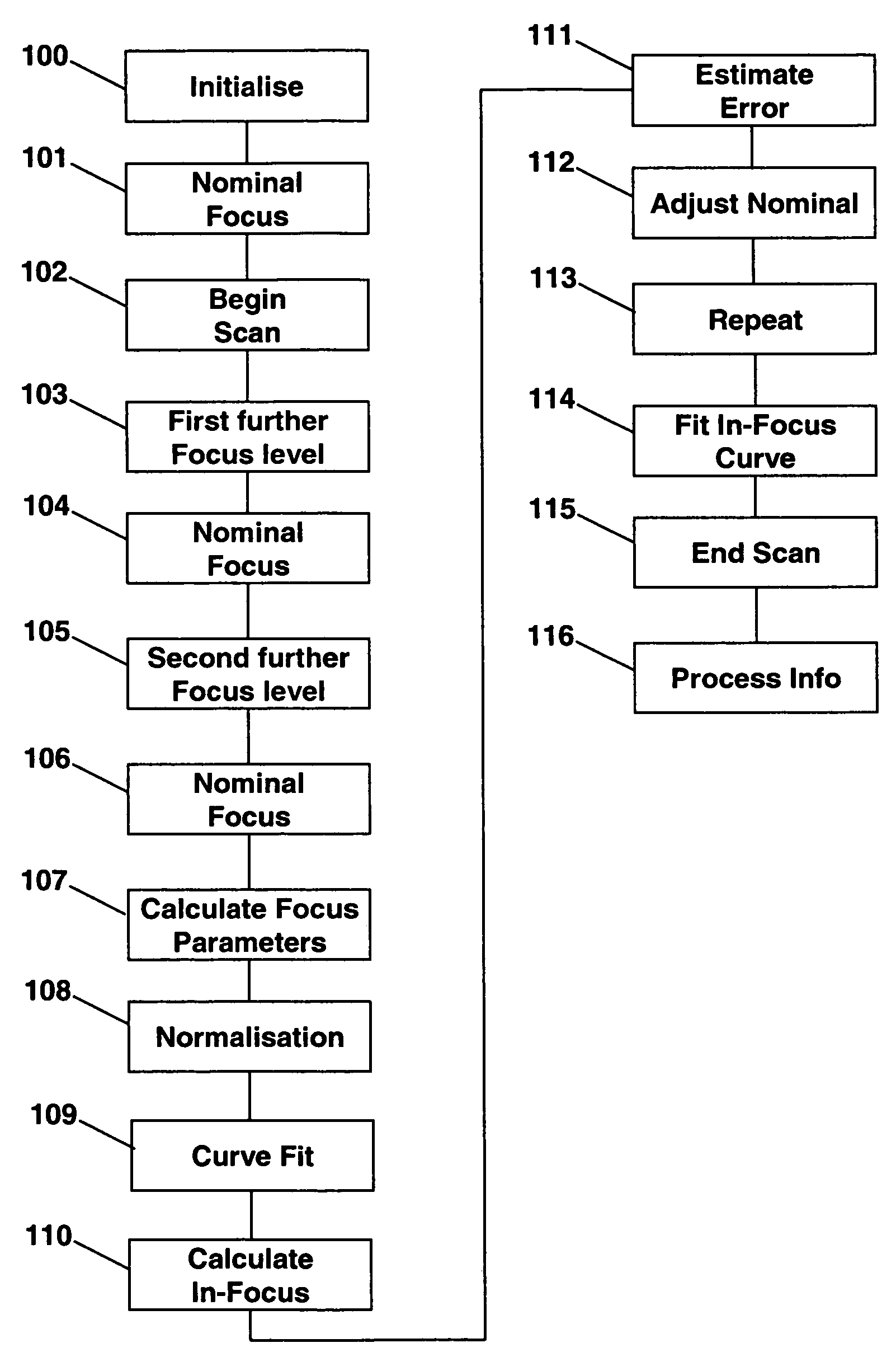
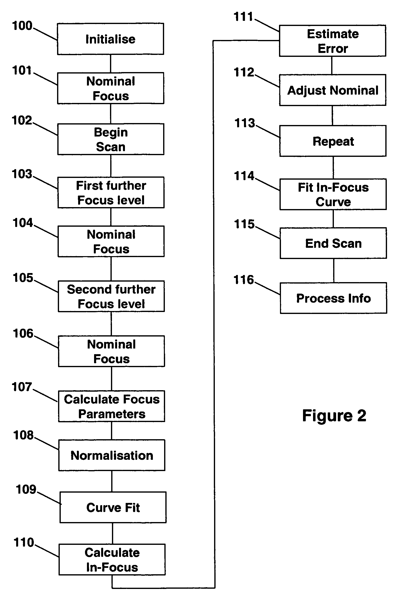
[0033]The operation of the image scanning apparatus 1 in performing a method according to the invention will now be described with reference to the flow diagram of FIG. 2. The method begins at step 100 where various setup and initialisation procedures are performed, including positioning the target 6 upon the platen 5. The controller 10 moves the scan head 2 by means of the drive mechanism 7 to a start position. This step may also optionally in...


PUM


Abstract

A method is provided of estimating an in-focus position of a target in an image scanning apparatus. A first part of the target is scanned at a nominal focus level so as to obtain corresponding image information. One or more further parts of the target are scanned at one or more respective further focus levels so as to obtain corresponding image information. A focus parameter is then calculated for each of the nominal and the one or more further focus levels using the respective image information. An in-focus position common to each of the first and further parts of the target is then estimated using the calculated focus parameters. Corresponding apparatus for performing the method is also provided.

Description

FIELD OF THE INVENTION[0001]The present invention relates to a method of estimating an in-focus position of a target in an image scanning apparatus, together with apparatus for performing the method.DESCRIPTION OF THE RELATED ART[0002]There are many situations where image scanning apparatus is used to obtain an image of a target. In many instances the depth of focus provided by the optical arrangement of the apparatus turns out to be less than the variation in the position of the target being scanned. For a substantially opaque target, this can be thought of as the height of the surface varying at different points within the scan by an amount greater than the depth of focus of the apparatus. In order to produce an image of the target the focus needs to be adjusted during the scan.[0003]It is known in the art to use a “focus map” at a number of points within the sample. The focus is measured and the focus between these points is predicted using interpolation techniques. The drawback ...

Claims


Application Information

Patent Timeline
Patent Type & Authority Patents(United States)
IPC IPC(8): G02B7/28H04N7/18G02B7/38
CPCG02B7/38H04N1/00013H04N1/00047H04N1/0005H04N1/00063H04N1/00068H04N1/00087H04N1/02409
Inventor GOUCH, MARTIN PHILIP
Owner FFEI LTD
Why Eureka
Eureka Blog
Learn More