Energy imaging with controlled rise and fall times

a technology of energy imaging and time-dependent rise and fall, applied in the field of imaging systems, can solve problems such as unsatisfactory image quality artifacts, and achieve the effect of reducing the variation from one view to the other and producing kv waveforms

Active Publication Date: 2018-06-05
GENERAL ELECTRIC CO
View PDF6 Cites 20 Cited by
  • Summary
  • Abstract
  • Description
  • Claims
  • Application Information

AI Technical Summary

Benefits of technology

[0007]In the present invention, rise times and fall times provided by a high voltage generator, such as during “dual energy” or multi-energy scans, are controlled to maintain image quality during such scans. The rise and fall times are controlled by first measuring rise and fall times at each transition. Then, a closed-loop controller is used to adjust control parameters, such as of the high voltage generator, based on an error determined from the measurement, to achieve substantially constant rise and fall times. This invention may be based on the implementation of two closed-loop controllers on rise and fall time of fast-kV exposures. As a result, image quality may be improved and system calibration time may be reduced.
[0009]A conventional closed-loop proportional-integral (PI) controller architecture or proportional-integral-derivative (PID) architecture could be used. After few cycles, the system may stabilize and the rise and fall distributions may become centered on target. Accordingly, the impact of hardware variations or disturbances, such as HV (high voltage) capacitance variations, temperature changes, electrical network fluctuations, and the like, may be minimized. Improved image quality due to better fidelity of tube voltage from one exposure to another and from one system to another may be provided.

Problems solved by technology

In CT imaging, variations of kV waveforms from one view to another may cause undesirable image quality artifacts.

Method used


Image

  • Energy imaging with controlled rise and fall times
  • Energy imaging with controlled rise and fall times
  • Energy imaging with controlled rise and fall times

Examples


Embodiment Construction

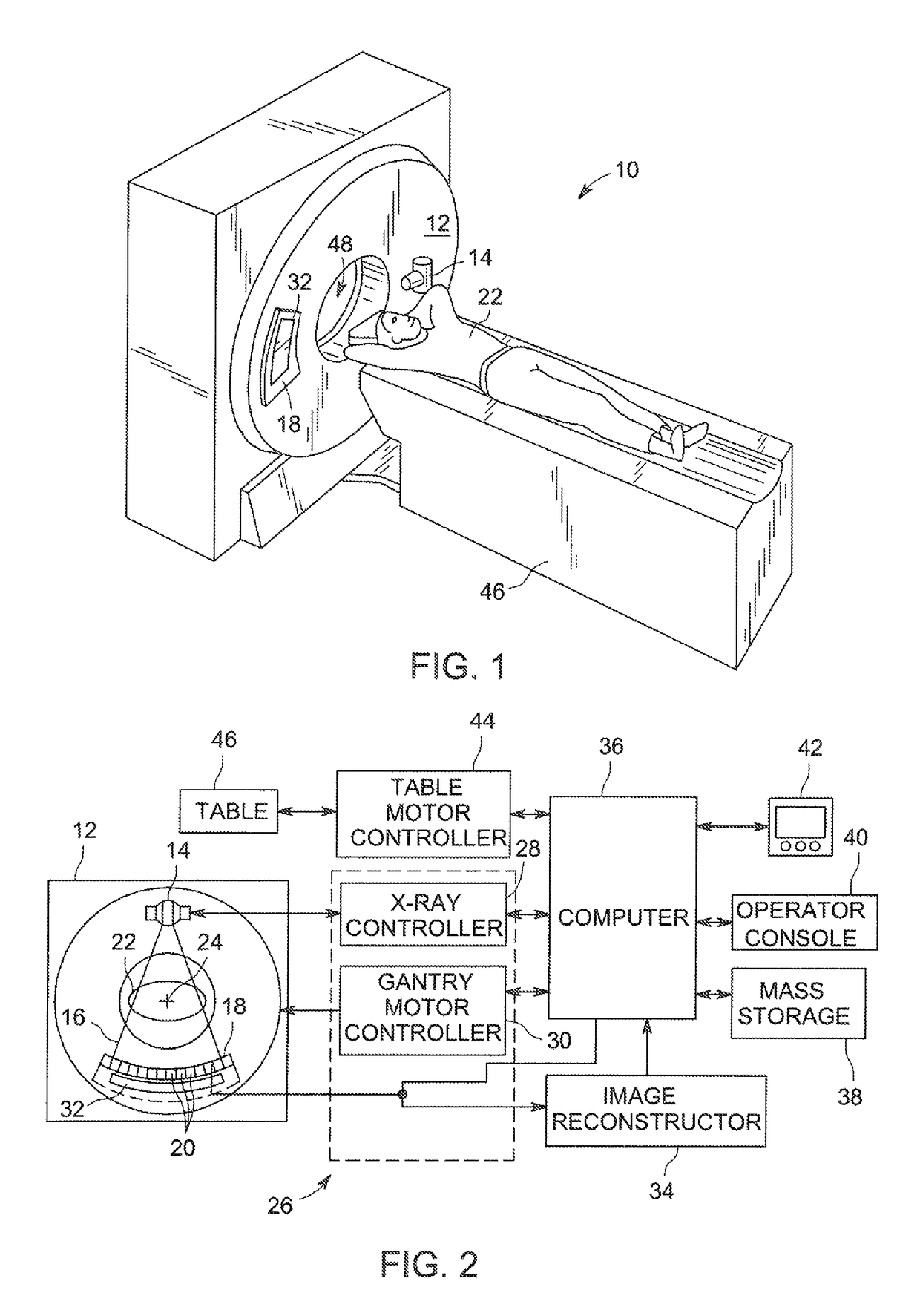
[0018]Referring now to FIG. 1, an exemplary computed tomography (CT) imagining system 10 is shown as including a gantry 12 which may be representative of a “third generation” CT scanner. The gantry 12 includes an X-ray source 14 which projects a polychromatic beam of X-rays 16 toward a detector assembly 18 on an opposite side of the gantry 12. Typically, a collimator may be an integral part of the detector assembly 18. Referring also to FIG. 2, the detector assembly 18 may be formed by a plurality of detectors 20 and data acquisition systems (DAS) 32. The plurality of detectors 20 sense the projected X-rays which pass through a patient 22 or object, and the DAS 32 converts corresponding data to digital signals for subsequent processing. Each detector 20 produces an analog electrical signal that represents the intensity of an impinging X-ray beam, and hence the attenuated beam as it passes through the patient 22. During a scan to acquire X-ray projection data, the gantry 12 and the c...


PUM


Abstract

Rise times and fall times provided by a high voltage generator are controlled to maintain image quality during such scans. The rise and fall times are controlled by first measuring rise and fall times at each transition. Then, a closed-loop controller is used to adjust control parameters of the high voltage generator, based on an error determined from the measurement, to achieve substantially constant rise and fall times. This invention may be based on the implementation of two closed-loop controllers on rise and fall time of fast-kV exposures. As a result, image quality may be improved and system calibration time may be reduced.

Description

CROSS-REFERENCE(S) TO RELATED APPLICATION(S)[0001]This application claims priority to U.S. Provisional Application No. 62 / 098,009, filed on Dec. 30, 2014, the disclosure of which is hereby incorporated by reference in its entirety.BACKGROUND OF THE INVENTION[0002]The invention relates generally to imaging systems, and more particularly to high voltage generators for imaging systems.[0003]Computed Tomography (CT) is an X-ray medical imaging process which makes possible obtaining a three-dimensional (3D) image of a patient or object using a plurality of two-dimensional (2D) images acquired about the patient or object. In CT, dual energy imaging is known for obtaining material characterizations and / or reduction of artifacts by utilizing two scans of the patient or object at different voltage / energy levels, “low-kV” and “high-kV.”[0004]In a single rotation around the patient or object, a high voltage generator switches between “low-kV” and “high-kV” in order to emit low energy X-rays an...

Claims


Application Information

Patent Timeline
Patent Type & Authority Patents(United States)
IPC IPC(8): H05G1/58H05G1/32
CPCH05G1/58H05G1/32G01N2223/419
Inventor LARROUX, JEAN-FRANCOISBOUHRAOUA, JULIENGADENNE, AURELIEN
Owner GENERAL ELECTRIC CO
Why Eureka
Try Eureka